INTERIOR PANELS / TRIM INSTRUMENT PANEL SAFETY PAD REMOVAL
CAUTION / NOTICE / HINT
- HINT:
- ·
Use the same procedure for RHD and LHD vehicles.
·The procedure listed below is for LHD vehicles.
PROCEDURE

 1. TABLE OF BOLT, SCREW AND NUT
- HINT:
-
All bolts, screws and nuts relevant to installing and removing the instrument panel are shown along with their alphabet code in the table below.
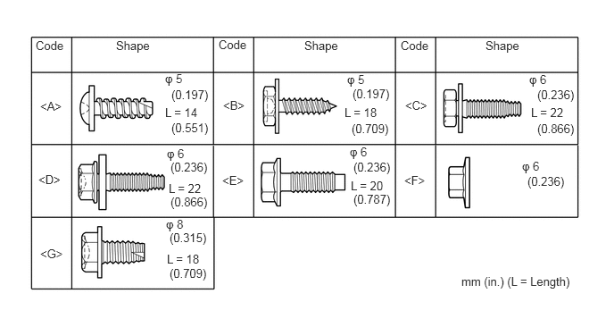
2. CUSTOMIZE POWER TILT AND POWER TELESCOPIC STEERING COLUMN SYSTEM
Disable the auto tilt away function by changing the customize parameter
Click hereSteering>STEERING COLUMN>POWER TILT AND POWER TELESCOPIC STEERING COLUMN SYSTEM>CUSTOMIZE PARAMETERS
- NOTICE:
-
Record the current customize parameter setting (whether the auto tilt away function is enabled or disabled) in order to restore the current setting after finishing the operation.
Turn the ignition switch to ON. Operate the tilt and telescopic switch to fully extend and lower the steering column assembly.
3. PRECAUTION
- CAUTION:
-
Wait at least 90 seconds after disconnecting the cable from the negative (-) battery terminal to disable the SRS system.
- NOTICE:
-
After turning the ignition switch off, waiting time may be required before disconnecting the cable from the negative (-) battery terminal.
-
Click hereGeneral>INTRODUCTION>REPAIR INSTRUCTION>PRECAUTION
4.DISCONNECT CABLE FROM NEGATIVE BATTERY TERMINAL
84140
5.REMOVE HEADLIGHT DIMMER SWITCH ASSEMBLY
6.REMOVE FRONT SEAT ASSEMBLY LH
for Manual Seat:
Click hereVehicle Interior>SEAT>FRONT SEAT ASSEMBLY (for Manual Seat)>REMOVAL
for Power Seat:
Click hereVehicle Interior>SEAT>FRONT SEAT ASSEMBLY (for Power Seat)>REMOVAL
7.REMOVE FRONT SEAT ASSEMBLY RH
for Manual Seat:
- HINT:
-
Use the same procedure described for the LH side.
for Power Seat:
- HINT:
-
Use the same procedure described for the LH side.
for Walk in Seat Type:
Click hereVehicle Interior>SEAT>FRONT SEAT ASSEMBLY (for Walk in Seat Type)>REMOVAL
58191
8.REMOVE FRONT FLOOR FOOTREST
for LHD:
Click hereVehicle Interior>INTERIOR PANELS / TRIM>FRONT FLOOR FOOTREST>REMOVAL
for RHD:
Click hereVehicle Interior>INTERIOR PANELS / TRIM>FRONT FLOOR FOOTREST>REMOVAL
58910C
9.REMOVE REAR CONSOLE BOX ASSEMBLY
for Automatic Transmission:
Click hereVehicle Interior>INTERIOR PANELS / TRIM>FRONT CONSOLE BOX(for Automatic Transmission)>REMOVAL
for Manual Transmission:
Click hereVehicle Interior>INTERIOR PANELS / TRIM>FRONT CONSOLE BOX(for Manual Transmission)>REMOVAL
w/ Refrigerated Cool Box:
Click hereVehicle Interior>INTERIOR PANELS / TRIM>FRONT CONSOLE BOX (w/ Refrigerated Cool Box)>REMOVAL
for Bench Seat Type:
Click hereVehicle Interior>INTERIOR PANELS / TRIM>FRONT CONSOLE BOX(for Bench Seat Type)>REMOVAL
67920
10.REMOVE DOOR SCUFF PLATE ASSEMBLY LH
67910
11.REMOVE DOOR SCUFF PLATE ASSEMBLY RH
- HINT:
-
Use the same procedure described for the LH side.
62112
12.REMOVE COWL SIDE TRIM BOARD LH
62111C
13.REMOVE COWL SIDE TRIM BOARD RH
- HINT:
-
Use the same procedure described for the LH side.
62312B
14.REMOVE FRONT DOOR OPENING TRIM WEATHERSTRIP LH
62311B
15.REMOVE FRONT DOOR OPENING TRIM WEATHERSTRIP RH
- HINT:
-
Use the same procedure described for the LH side.
74616C
16.REMOVE FRONT NO. 1 ASSIST GRIP PLUG LH
74615E
17.REMOVE FRONT NO. 1 ASSIST GRIP PLUG RH
- HINT:
-
Use the same procedure described for the LH side.
74611F
18.REMOVE NO. 1 ASSIST GRIP
62212
19.REMOVE FRONT PILLAR GARNISH LH
62211
20.REMOVE FRONT PILLAR GARNISH RH
- HINT:
-
Use the same procedure described for the LH side.
86160J
21.REMOVE FRONT NO. 3 SPEAKER ASSEMBLY
55318C
22.REMOVE INSTRUMENT SIDE PANEL LH

|
Protective Tape |
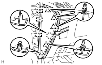
Put protective tape around the instrument side panel LH.
Using a moulding remover, detach the 5 clips, claw and 3 guides and remove the instrument side panel LH.
55471A
23.REMOVE INSTRUMENT CLUSTER FINISH PANEL ORNAMENT (for LHD)
|
|
Protective Tape |
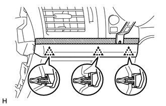
Put protective tape around the instrument cluster finish panel ornament.
Using a moulding remover, detach the 3 clips and remove the instrument cluster finish panel ornament.
55476C
24.REMOVE INSTRUMENT PANEL FINISH PLATE GARNISH (for RHD)
w/ Entry and Start System:
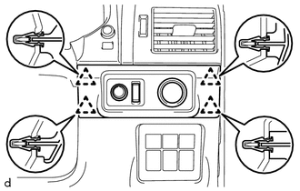
Detach the 4 clips.
Disconnect each connector and remove the instrument panel finish plate garnish.
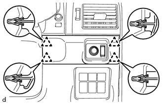
w/o Entry and Start System:
Detach the 4 clips.
Disconnect each connector and remove the instrument panel finish plate garnish.
55480D
25.REMOVE LOWER INSTRUMENT PANEL FINISH PANEL ASSEMBLY
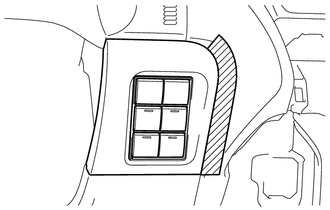
|
|
Protective Tape |
Put protective tape around the lower instrument panel finish panel assembly.
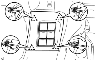
Detach the 4 clips.
Disconnect each connector and remove the lower instrument panel finish panel assembly.
55045
26.REMOVE LOWER INSTRUMENT PANEL FINISH PANEL SUB-ASSEMBLY
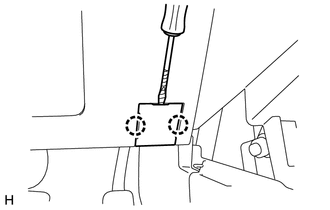
|
|
Protective Tape |
Using a screwdriver, detach the 2 claws and open the cover.
- HINT:
-
Tape the screwdriver tip before use.
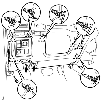
w/o Knee Airbag:
Remove the 2 bolts <C>.
Detach the 7 clips.
Disconnect each connector and each cable and remove the lower instrument panel finish panel sub-assembly.
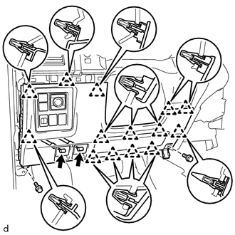
w/ Knee Airbag:
Remove the 2 bolts <C>.
Detach the 14 clips.
Disconnect each connector and each cable and remove the lower instrument panel finish panel sub-assembly.
73900
27.REMOVE LOWER NO. 1 INSTRUMENT PANEL AIRBAG ASSEMBLY (w/ Knee Airbag)
55404D
28.REMOVE INSTRUMENT CLUSTER FINISH PANEL SUB-ASSEMBLY
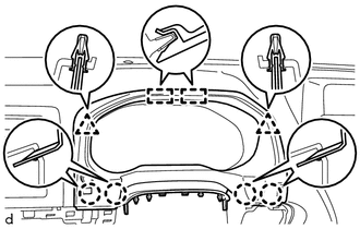
except 5L-E:
Detach the 4 claws, 2 clips and 2 guides and remove the instrument cluster finish panel sub-assembly.
Disconnect the connector.
for 5L-E:
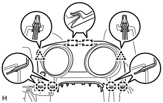
Detach the 4 claws, 2 clips and 2 guides and remove the instrument cluster finish panel sub-assembly.
Disconnect the connector.
83100
29.REMOVE COMBINATION METER ASSEMBLY
55317A
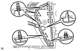
30.REMOVE INSTRUMENT SIDE PANEL RH
|
|
Protective Tape |
Put protective tape around the instrument side panel RH.
Using a moulding remover, detach the 5 clips, claw and 3 guides.
Disconnect the connector and remove the instrument side panel RH.
55461A
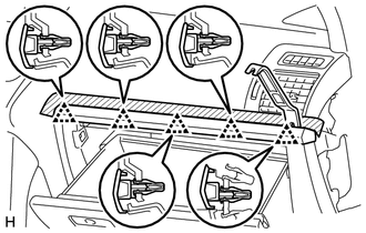
31.REMOVE INSTRUMENT PANEL ORNAMENT
|
|
Protective Tape |
Put protective tape around the instrument panel ornament.
Using a moulding remover, detach the 5 clips and remove the instrument panel ornament.
55550
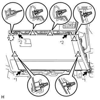
32.REMOVE GLOVE COMPARTMENT DOOR ASSEMBLY
| *1 | Bolt |
| *2 | Screw |
Remove the 2 bolts <C> and 2 screws <A> or <B>.
Detach the 5 clips and claw.
Disconnect each connector and remove the glove compartment door assembly.
86681C
33.REMOVE ANTENNA DIVIDER (w/ Antenna Divider)
85940
34.REMOVE WINDSHIELD WIPER RELAY ASSEMBLY (w/ Wiper ECU)
85970A
35.REMOVE DOUBLE LOCK DOOR CONTROL RELAY ASSEMBLY (w/ Telematics Transceiver, Double Door Lock)
36.REMOVE TELEPHONE TRANSCEIVER ASSEMBLY WITH BRACKET (w/ Telematics Transceiver)
89533
37.REMOVE 4 WHEEL DRIVE CONTROL ECU
55420A
38.REMOVE CENTER INSTRUMENT CLUSTER FINISH PANEL ASSEMBLY (w/o Audio)
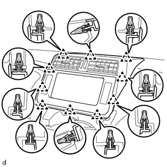
Detach the 10 clips and remove the center instrument cluster finish panel assembly.
Disconnect each connector.
55420A
39.REMOVE CENTER INSTRUMENT CLUSTER FINISH PANEL ASSEMBLY (for Radio Receiver Type)
- HINT:
-
Use the same procedure described for the center instrument cluster finish panel (w/o Audio).
55522B
40.REMOVE RADIO TUNER OPENING COVER (w/o Audio)
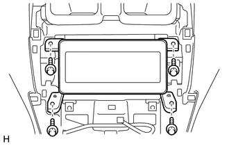
Remove the 4 bolts and radio tuner opening cover.
86120
41.REMOVE RADIO RECEIVER ASSEMBLY (for Radio Receiver Type)
42.REMOVE RADIO AND DISPLAY RECEIVER ASSEMBLY WITH BRACKET (for Radio and Display Type)
55406B
43.REMOVE LOWER CENTER INSTRUMENT CLUSTER FINISH PANEL SUB-ASSEMBLY (w/o Module Switch)
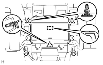
Remove the 2 bolts <E>.
Detach the 3 clips and guide and remove the lower center instrument cluster finish panel sub-assembly.
84970
44.REMOVE COMBINATION SWITCH ASSEMBLY (w/ Module Switch)
55421B
45.REMOVE UPPER INSTRUMENT CLUSTER FINISH PANEL
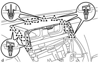
Detach the 8 clips and 3 guides and remove the upper instrument cluster finish panel.
86160L
46.REMOVE FRONT NO. 4 SPEAKER ASSEMBLY
55650
47.REMOVE NO. 1 INSTRUMENT PANEL REGISTER ASSEMBLY
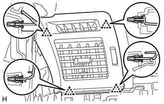
Detach the 4 clips and remove the No. 1 instrument panel register assembly.
55660
48.REMOVE NO. 2 INSTRUMENT PANEL REGISTER ASSEMBLY
- HINT:
-
Use the same procedure described for the No. 1 instrument panel register assembly.
55408F
49.REMOVE NO. 1 INSTRUMENT PANEL SPEAKER PANEL SUB-ASSEMBLY
|
|
Protective Tape |
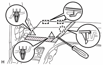
Put protective tape around the No. 1 instrument panel speaker panel sub-assembly.
Using a screwdriver, detach the 2 clips, claw, and 2 guides and remove the No. 1 instrument panel speaker panel sub-assembly.
- HINT:
-
Tape the screwdriver tip before use.
55409F
50.REMOVE NO. 2 INSTRUMENT PANEL SPEAKER PANEL SUB-ASSEMBLY
- HINT:
-
Use the same procedure described for the No. 1 instrument panel speaker panel sub-assembly.
86160P
51.REMOVE FRONT NO. 2 SPEAKER ASSEMBLY
55401E
52.REMOVE INSTRUMENT PANEL SAFETY PAD SUB-ASSEMBLY
for LHD:
Partially remove the floor carpet.
- HINT:
-
It is not necessary to fully remove the floor carpet. Partially remove it so that the No. 2 instrument panel wire can be removed in a later step.
Remove the 6 bolts <E> and nut <F>.
Remove the 2 passenger airbag bolts <G>.
Remove the 4 bolts, 2 nuts and 2 brackets.
Disconnect the connectors and detach the clamps and claws.
Detach the 2 guides and remove the instrument panel safety pad sub-assembly.
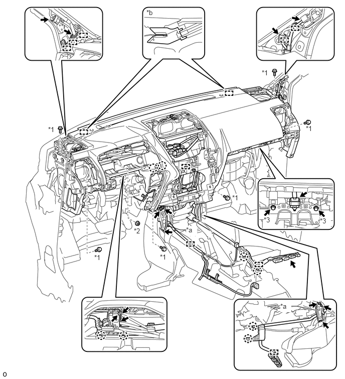
| *1 | Bolt <E> | *2 | Nut <F> |
| *3 | Bolt <G> | - | - |
| *a | Bracket | *b | Guide |
for RHD:
Partially remove the floor carpet.
- HINT:
-
It is not necessary to fully remove the floor carpet. Partially remove it so that the No. 2 instrument panel wire can be removed in a later step.
Remove the 6 bolts <E> and nut <F>.
Remove the 2 passenger airbag bolts <G>.
Remove the 4 bolts, 2 nuts and 2 brackets.
Disconnect the connectors and detach the clamps and claws.
Detach the 2 guides and remove the instrument panel safety pad sub-assembly.
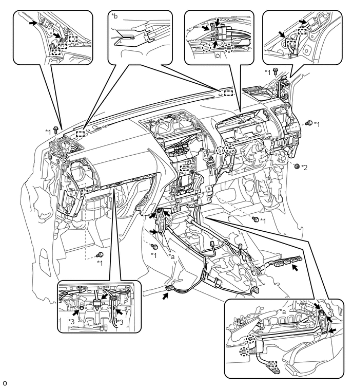
| *1 | Bolt <E> | *2 | Nut <F> |
| *3 | Bolt <G> | - | - |
| *a | Bracket | *b | Guide |