INTERIOR PANELS / TRIM ROOF HEADLINING(for 5 Door) REMOVAL
CAUTION / NOTICE / HINT
- HINT:
- ·
Use the same procedure for RHD and LHD vehicles.
·The procedure listed below is for LHD vehicles.
PROCEDURE

 1. PRECAUTION
- CAUTION:
-
Wait at least 90 seconds after disconnecting the cable from the negative (-) battery terminal to disable the SRS system.
- NOTICE:
-
After turning the ignition switch off, waiting time may be required before disconnecting the cable from the negative (-) battery terminal.
-
Click hereGeneral>INTRODUCTION>REPAIR INSTRUCTION>PRECAUTION
2.DISCONNECT CABLE FROM NEGATIVE BATTERY TERMINAL
3.REMOVE REAR NO. 2 SEAT ASSEMBLY (w/ Rear No. 2 Seat)
for Manual Seat Type:
Click hereVehicle Interior>SEAT>REAR NO. 2 SEAT ASSEMBLY (for Manual Seat Type LH Side)>REMOVAL
for Power Seat Type:
Click hereVehicle Interior>SEAT>REAR NO. 2 SEAT ASSEMBLY (for Power Seat Type LH Side)>REMOVAL
for Face to Face Seat Type:
Click hereVehicle Interior>SEAT>REAR NO. 2 SEAT ASSEMBLY(for Face to Face Seat Type)>REMOVAL
4.REMOVE REAR NO. 1 SEAT ASSEMBLY (w/ Rear No. 1 Seat)
for 60/40 Split Slide Walk-in Seat Type LH Side:
for 60/40 Split Slide Walk-in Seat Type RH Side:
5.REMOVE REAR NO. 1 SEATBACK ASSEMBLY (w/ Rear No. 1 Seat)
for 60/40 Split Double-folding Seat Type LH Side:
for 60/40 Split Double-folding Seat Type RH Side:
67920
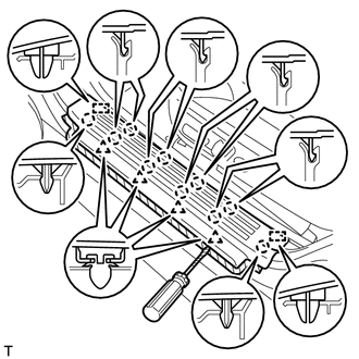
6.REMOVE DOOR SCUFF PLATE ASSEMBLY LH

|
Protective Tape |
Put protective tape around the door scuff plate assembly LH.
Using a screwdriver, detach the 4 clips, 10 claws and 2 guides and remove the door scuff plate assembly LH.
- HINT:
-
Tape the screwdriver tip before use.
67910
7.REMOVE DOOR SCUFF PLATE ASSEMBLY RH
- HINT:
-
Use the same procedure described for the LH side.
62112
8.REMOVE COWL SIDE TRIM BOARD LH
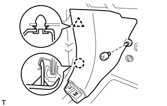
Remove the clip.
Detach the clip and claw and remove the cowl side trim board LH.
62111C
9.REMOVE COWL SIDE TRIM BOARD RH
- HINT:
-
Use the same procedure described for the LH side.
62312B
10.REMOVE FRONT DOOR OPENING TRIM WEATHERSTRIP LH
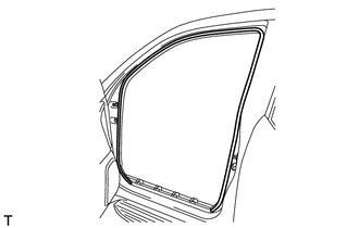
Remove the front door opening trim weatherstrip LH.
62311B
11.REMOVE FRONT DOOR OPENING TRIM WEATHERSTRIP RH
- HINT:
-
Use the same procedure described for the LH side.
74616C
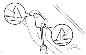
12.REMOVE FRONT NO. 1 ASSIST GRIP PLUG LH
|
|
Protective Tape |
- HINT:
-
Use the same procedure for the other front No. 1 assist grip plug.
Using a screwdriver, detach the 2 claws and remove the front No. 1 assist grip plug LH.
- HINT:
-
Tape the screwdriver tip before use.
74615E
13.REMOVE FRONT NO. 1 ASSIST GRIP PLUG RH
- HINT:
-
Use the same procedure described for the LH side.
74611F
14.REMOVE NO. 1 ASSIST GRIP
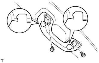
- HINT:
-
Use the same procedure for the other No. 1 assist grip.
Remove the 2 bolts.
Detach the 2 claws and remove the No. 1 assist grip.
62212
15.REMOVE FRONT PILLAR GARNISH LH
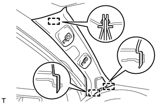
Detach the 3 guides and remove the front pillar garnish LH.
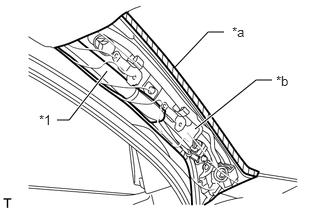
| *1 | Curtain Shield Airbag Assembly |
| *a | Adhesive Tape |
| *b | Protective Cover |
w/ Curtain Shield Airbag:
Protect the curtain shield airbag assembly.
Completely cover the airbag with a cloth or nylon sheet and secure the ends of the cover with adhesive tape as shown in the illustration.
- NOTICE:
-
Cover the curtain shield airbag with a protective cover as soon as the front pillar garnish is removed.
62211
16.REMOVE FRONT PILLAR GARNISH RH
- HINT:
-
Use the same procedure described for the LH side.
58371F
17.REMOVE REAR NO. 1 FLOOR STEP COVER (w/ Rear No. 2 Seat)
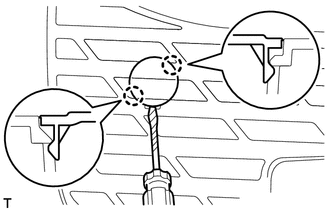
|
|
Protective Tape |
- HINT:
-
Use the same procedure for all rear No. 1 floor step covers.
Using a screwdriver, detach the 2 claws and remove the rear No. 1 floor step cover.
- HINT:
-
Tape the screwdriver tip before use.
67934
18.REMOVE INSIDE QUARTER SCUFF PLATE LH (w/ Rear No. 2 Seat)
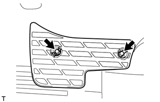
Remove the 2 bolts and inside quarter scuff plate LH.
67933
19.REMOVE INSIDE QUARTER SCUFF PLATE RH (w/ Rear No. 2 Seat)
- HINT:
-
Use the same procedure described for the LH side.
67918D
20.REMOVE REAR DOOR SCUFF PLATE LH
|
|
Protective Tape |
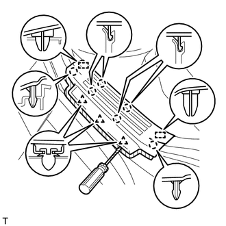
Put protective tape around the rear door scuff plate LH.
Using a screwdriver, detach the 3 clips, 6 claws and 2 guides and remove the rear door scuff plate LH.
- HINT:
-
Tape the screwdriver tip before use.
67917C
21.REMOVE REAR DOOR SCUFF PLATE RH
- HINT:
-
Use the same procedure described for the LH side.
62332C
22.REMOVE REAR DOOR OPENING TRIM WEATHERSTRIP LH
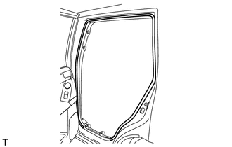
Remove the rear door opening trim weatherstrip LH.
62331C
23.REMOVE REAR DOOR OPENING TRIM WEATHERSTRIP RH
- HINT:
-
Use the same procedure described for the LH side.
73233
24.REMOVE OUTER LAP BELT ANCHOR COVER
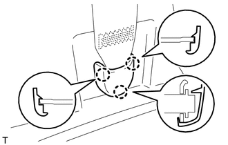
- HINT:
-
Use the same procedure for the other outer lap belt anchor cover.
Detach the 3 claws and remove the outer lap belt anchor cover.
62414A
25.REMOVE LOWER CENTER PILLAR GARNISH LH
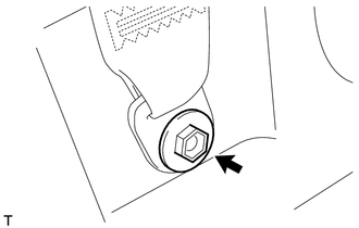
Remove the bolt and disconnect the front seat outer belt floor anchor.
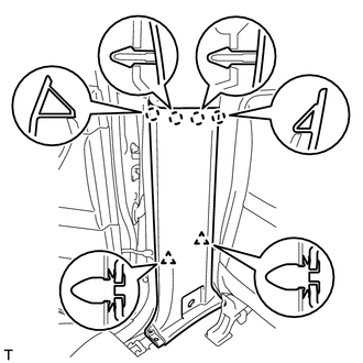
Detach the 4 claws and 2 clips and remove the lower center pillar garnish LH.
62413A
26.REMOVE LOWER CENTER PILLAR GARNISH RH
- HINT:
-
Use the same procedure described for the LH side.
74638
27.REMOVE NO. 2 ASSIST GRIP PLUG LH
|
|
Protective Tape |
- HINT:
-
Use the same procedure for the other front No. 2 assist grip plug.
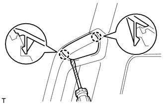
Using a screwdriver, detach the 2 claws and remove the front No. 2 assist grip plug LH.
- HINT:
-
Tape the screwdriver tip before use.
74637
28.REMOVE NO. 2 ASSIST GRIP PLUG RH
- HINT:
-
Use the same procedure described for the LH side.
74611G
29.REMOVE NO. 2 ASSIST GRIP
- HINT:
-
Use the same procedure for the other No. 2 assist grip.
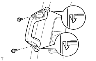
Remove the 2 bolts.
Detach the 2 claws and remove the No. 2 assist grip.
62412
30.REMOVE CENTER PILLAR GARNISH LH
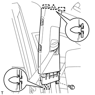
Move the front shoulder belt anchor adjuster to the lowest position.
Remove the bolt.
Detach the 2 clips and 2 guides.
Pass the front seat outer belt floor anchor through the center pillar garnish and remove the center pillar garnish LH.
62411
31.REMOVE CENTER PILLAR GARNISH RH
- HINT:
-
Use the same procedure described for the LH side.
64910M
32.REMOVE TONNEAU COVER ASSEMBLY (w/ Tonneau Cover)
Remove the tonneau cover assembly.
64717A
33.REMOVE FRONT LUGGAGE COMPARTMENT TRIM COVER (w/o Rear No. 2 Seat)
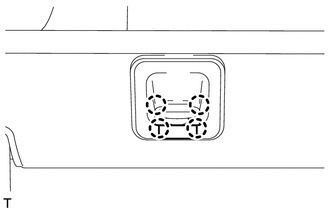
- HINT:
-
Use the same procedure for the other front luggage compartment trim cover.
Detach the 4 claws and remove the cap.
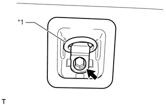
| *1 | Luggage Hold Belt Striker |
Remove the bolt, luggage hold belt striker and front luggage compartment trim cover.
58401A
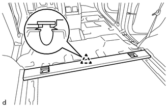
34.REMOVE NO. 1 DECK BOARD SUB-ASSEMBLY (w/o Rear No. 2 Seat)
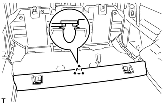
w/o Rear Air Conditioning System:
Detach the clip and remove the No. 1 deck board sub-assembly.
w/ Rear Air Conditioning System:
Detach the clip and remove the No. 1 deck board sub-assembly.
58574A
35.REMOVE REAR FLOOR MAT REAR SUPPORT PLATE (w/o Rear No. 2 Seat)
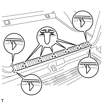
Detach the 5 clips and 4 claws and remove the rear floor mat rear support plate.
57412C
36.REMOVE FLOOR SIDE RAIL LH (w/ Deck Rail)
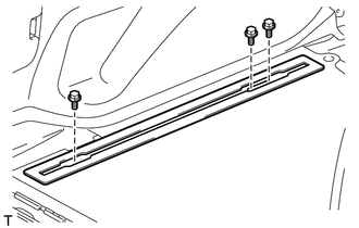
Remove the 3 bolts and floor side rail LH.
57411D
37.REMOVE FLOOR SIDE RAIL RH (w/ Deck Rail)
- HINT:
-
Use the same procedure described for the LH side.
58570C
38.REMOVE REAR FLOOR CARPET ASSEMBLY (w/o Rear No. 2 Seat)
Detach the 4 claws and remove the rear floor carpet assembly.
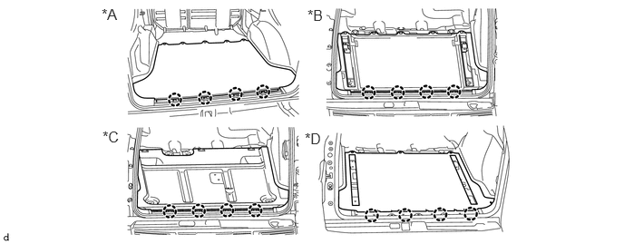
| *A | w/o Deck Rail | *B | w/ Deck Rail |
| *C | for Face to Face Seat Type | *D | w/ Rear Air Conditioning System |
73233A
39.REMOVE REAR NO. 1 SEAT OUTER LAP BELT ANCHOR COVER
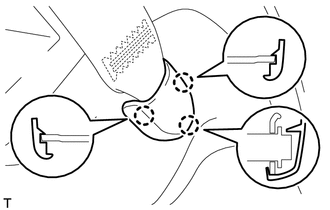
- HINT:
-
Use the same procedure for the other rear No. 1 seat outer lap belt anchor cover.
Detach the 3 claws and remove the rear No. 1 seat outer lap belt anchor cover.
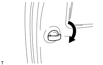
64725D
40.REMOVE NO. 1 LUGGAGE COMPARTMENT TRIM HOOK
- HINT:
-
Use the same procedure for the other No. 1 luggage compartment trim hook.
Remove the No. 1 luggage compartment trim hook by turning it clockwise.
64937A
41.REMOVE NO. 1 TONNEAU COVER HOLDER CAP (w/o Tonneau Cover)
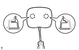
|
|
Protective Tape |
- HINT:
-
Use the same procedure for the other No. 1 tonneau cover holder cap.
Using a screwdriver, detach the 2 claws and remove the No. 1 tonneau cover holder cap.
- HINT:
-
Tape the screwdriver tip before use.
64712F
42.REMOVE FRONT DECK SIDE TRIM COVER (w/ Tonneau Cover)
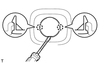
|
|
Protective Tape |
- HINT:
-
Use the same procedure for the other front deck side trim cover.
Using a screwdriver, detach the 2 claws and remove the front deck side trim cover.
- HINT:
-
Tape the screwdriver tip before use.
74617A
43.REMOVE ASSIST GRIP PLUG (w/ Rear No. 2 Seat)
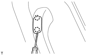
|
|
Protective Tape |
- HINT:
-
Use the same procedure for all assist grip plugs.
Using a screwdriver, detach the 2 claws and remove the assist grip plug.
- HINT:
-
Tape the screwdriver tip before use.
74603C
44.REMOVE ASSIST GRIP SUB-ASSEMBLY (w/ Rear No. 2 Seat)
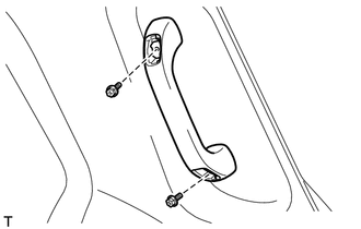
- HINT:
-
Use the same procedure for the other assist grip sub-assembly.
Remove the 2 bolts and assist grip sub-assembly.
88625Q
45.REMOVE COOLER THERMISTOR (ROOM TEMPERATURE SENSOR) (w/ Rear Air Conditioning System)
64740C
46.REMOVE DECK TRIM SIDE PANEL ASSEMBLY LH
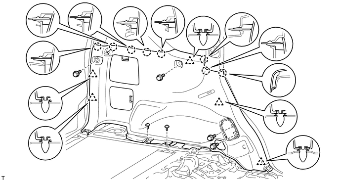
w/o Rear No. 2 Seat, w/o Rear Air Conditioning System:
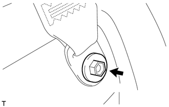
Remove the bolt and disconnect the rear No. 1 seat outer belt floor anchor.
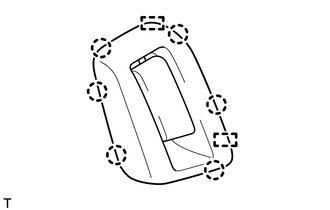
Detach the 6 claws and 2 guides and disconnect the rear seatback lock control lever base.
Remove the 4 bolts and 2 screws.
Detach the 5 clips and 8 claws.
Pass the rear seatback lock control lever base through the deck trim side panel assembly and remove the deck trim side panel assembly LH.
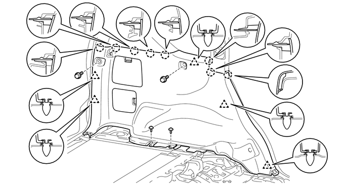
w/o Rear No. 2 Seat, w/ Rear Air Conditioning System:
Remove the bolt and disconnect the rear No. 1 seat outer belt floor anchor.
Remove the 2 bolts and 2 screws.
Detach the 5 clips and 8 claws and remove the deck trim side panel assembly LH.
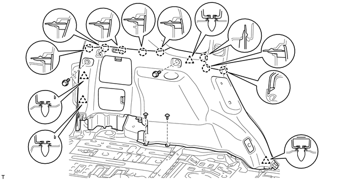
w/ Rear No. 2 Seat:
Remove the bolt and disconnect the rear No. 1 seat outer belt floor anchor.
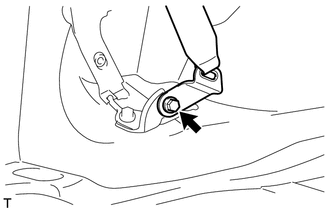
Remove the bolt and disconnect the rear No. 2 seat outer belt floor anchor.
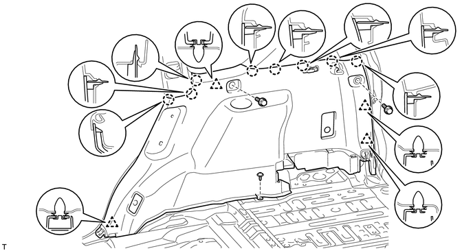
Remove the 2 bolts and 2 screws.
Detach the 4 clips and 8 claws and remove the deck trim side panel assembly LH.
64730B
47.REMOVE DECK TRIM SIDE PANEL ASSEMBLY RH
w/o Rear No. 2 Seat, w/o Rear Air Conditioning System:
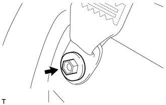
Remove the bolt and disconnect the rear No. 1 seat outer belt floor anchor.
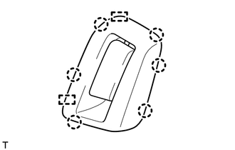
Detach the 6 claws and 2 guides and disconnect the rear seatback lock control lever base.
Remove the 4 bolts and screw.
Detach the 5 clips and 8 claws.
Disconnect each connector.
Pass the rear seatback lock control lever base through the deck trim side panel and remove the deck trim side panel assembly RH.
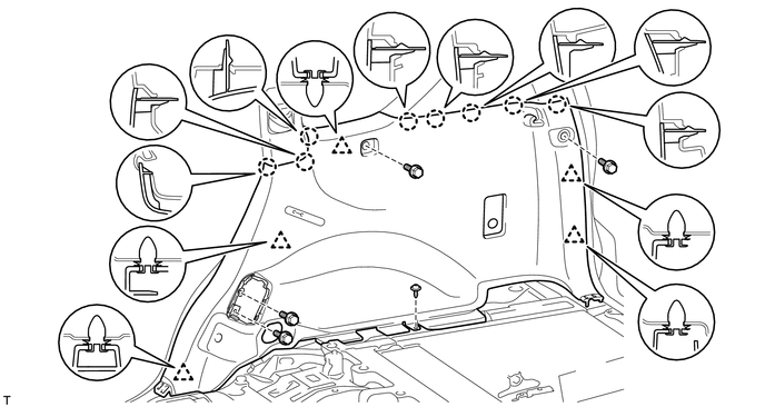
w/o Rear No. 2 Seat, w/ Rear Air Conditioning System:
Remove the bolt and disconnect the rear No. 1 seat outer belt floor anchor.
Remove the 2 bolts and screw.
Detach the 4 clips and 8 claws.
Disconnect each connector and remove the deck trim side panel assembly RH.
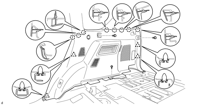
w/ Rear No. 2 Seat:
Remove the bolt and disconnect the rear No. 1 seat outer belt floor anchor.
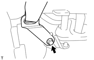
Remove the bolt and disconnect the rear No. 2 seat outer belt floor anchor.
Remove the 2 bolts and screw.
Detach the 4 clips and 8 claws.
Disconnect each connector and remove the deck trim side panel assembly RH.
62520P
48.REMOVE FRONT QUARTER TRIM PANEL ASSEMBLY LH
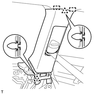
Move the rear shoulder belt anchor adjuster to the lowest position.
Detach the 2 clips and 2 guides.
Pass the rear No. 1 seat outer belt floor anchor through the front quarter trim panel and remove the front quarter trim panel assembly LH.
62510P
49.REMOVE FRONT QUARTER TRIM PANEL ASSEMBLY RH
- HINT:
-
Use the same procedure described for the LH side.
62640P
50.REMOVE REAR QUARTER TRIM PANEL ASSEMBLY LH
w/o Rear No. 2 Seat:
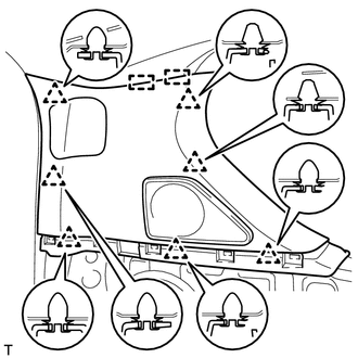
Detach the 7 clips and 2 guides and remove the rear quarter trim panel assembly LH.
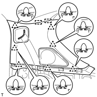
w/ Rear No. 2 Seat:
Detach the 7 clips and 2 guides.
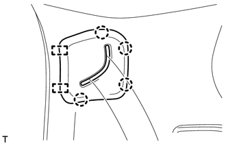
Detach the 4 clips and 2 guides, pass the rear No. 2 seat outer belt floor anchor through the rear quarter trim panel assembly LH and remove the rear quarter trim panel assembly LH.
62630P
51.REMOVE REAR QUARTER TRIM PANEL ASSEMBLY RH
- HINT:
-
Use the same procedure described for the LH side.
74610A
52.REMOVE ASSIST GRIP SUB-ASSEMBLY
- HINT:
-
Use the same procedure for the other assist grip sub-assembly.
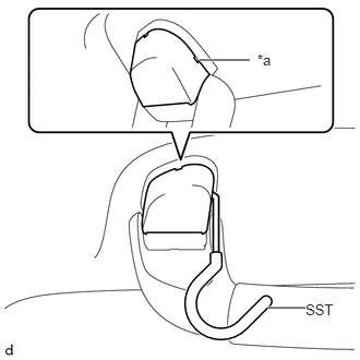
| *a | Cutout |
Insert SST into the cutout of the assist grip cover LH as shown in the illustration.
- SST
- 09813-00010
- NOTICE:
-
To prevent the assist grip sub-assembly from being damaged, make sure to insert SST straight into the cutout.
- HINT:
-
Use the same procedure for the claw on the other side of the assist grip cover LH.
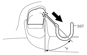
| *a | 30 to 45° |

|
Remove in this Direction |
Pull SST as shown in the illustration to detach the claw.
- NOTICE:
-
To prevent the assist grip sub-assembly from being damaged, make sure to only pull SST as shown in the illustration.
- HINT:
-
Use the same procedure for the claw on the other side of the assist grip cover LH.
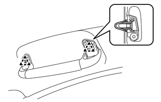
Detach the 2 clips and remove the assist grip sub-assembly.
74610U
53.REMOVE REAR ASSIST GRIP ASSEMBLY LH
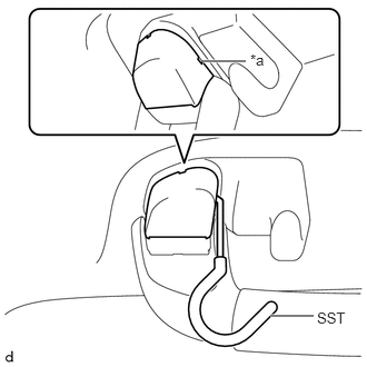
| *a | Cutout |
Insert SST into the cutout of the assist grip cover LH as shown in the illustration.
- SST
- 09813-00010
- NOTICE:
-
To prevent the rear assist grip sub-assembly LH from being damaged, make sure to insert SST straight into the cutout.
- HINT:
-
Use the same procedure for the claw on the other side of the assist grip cover LH.
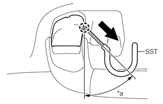
| *a | 30 to 45° |
|
|
Remove in this Direction |
Pull SST as shown in the illustration to detach the claw.
- NOTICE:
-
To prevent the rear assist grip sub-assembly LH from being damaged, make sure to only pull SST as shown in the illustration.
- HINT:
-
Use the same procedure for the claw on the other side of the assist grip cover LH.
Detach the 2 clips and remove the rear assist grip sub-assembly LH.
74610V
54.REMOVE REAR ASSIST GRIP ASSEMBLY RH
- HINT:
-
Use the same procedure described for the LH side.
74611B
55.REMOVE ASSIST GRIP (w/ Rear No. 2 Seat)
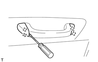
|
|
Protective Tape |
- HINT:
-
Use the same procedure for the other assist grip.
Using a screwdriver, detach the 4 claws and open the 2 covers.
- HINT:
-
Tape the screwdriver tip before use.
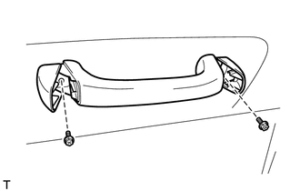
Remove the 2 bolts and assist grip.
81260A
56.REMOVE MAP LIGHT ASSEMBLY
89943
57.REMOVE RAIN SENSOR COVER (w/ Rain Sensor)
87834
58.REMOVE INNER REAR VIEW MIRROR STAY HOLDER COVER (w/ EC Mirror, w/o Pre-collision System)
86466E
59.REMOVE NO. 2 FORWARD RECOGNITION COVER (w/ Pre-collision System)
86466D
60.REMOVE NO. 1 FORWARD RECOGNITION COVER (w/ Pre-collision System)
81240
61.REMOVE NO. 1 ROOM LIGHT ASSEMBLY
81240D
62.REMOVE NO. 2 ROOM LIGHT ASSEMBLY
86295
63.REMOVE TELEVISION BASE (w/ Rear Seat Entertainment System)
87217D
64.REMOVE REAR SIDE NO. 1 AIR DUCT (w/ Rear Air Conditioning System)
86160T
65.REMOVE REAR HEADER SPEAKER ASSEMBLY (w/ Rear Air Conditioning System)
74318
66.REMOVE VISOR BRACKET COVER LH
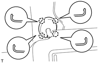
- HINT:
-
Use the same procedure for the other visor bracket cover.
Detach the 4 claws and remove the visor bracket cover LH.
74317
67.REMOVE VISOR BRACKET COVER RH
- HINT:
-
Use the same procedure described for the LH side.
74320
68.REMOVE VISOR ASSEMBLY LH
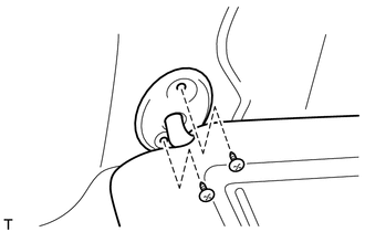
Remove the 2 screws and visor assembly LH.
74310
69.REMOVE VISOR ASSEMBLY RH
- HINT:
-
Use the same procedure described for the LH side.
74348
70.REMOVE VISOR HOLDER
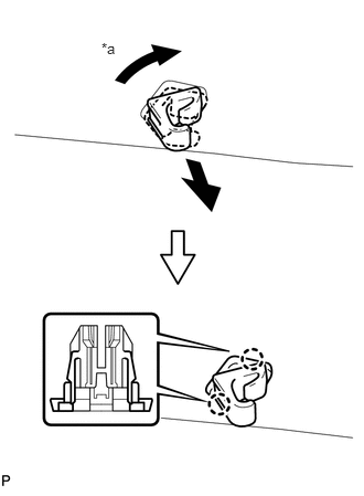
| *a | 45° |
- HINT:
-
Use the same procedure for the other visor holder.
Turn the visor holder approximately 45° and pull it out as shown in the illustration.
Detach the 2 claws and remove the visor holder.
63310
71.REMOVE ROOF HEADLINING ASSEMBLY
w/ Pre-collision System:
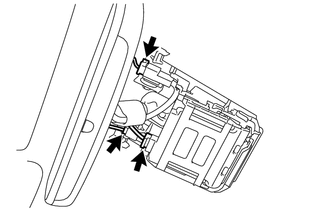
Disconnect the 3 connectors.
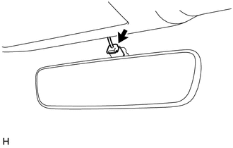
w/ EC Mirror:
Disconnect the inner mirror connector.
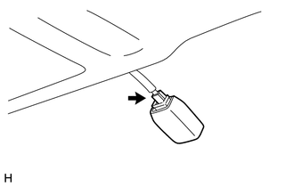
w/ Rain Sensor:
Disconnect the rain sensor connector.
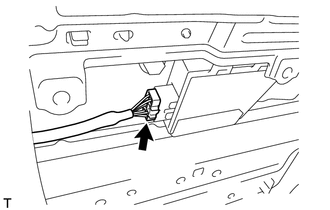
w/ Sliding Roof:
Disconnect the drive gear connector.
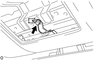
w/ Pre-collision System:
Remove the bolt.
Detach the hook and disconnect the camera earth.
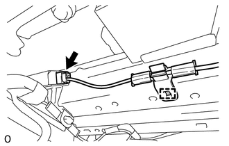
w/ Digital Audio Broadcasting Antenna:
Disconnect the connector and detach the wire harness clamp.
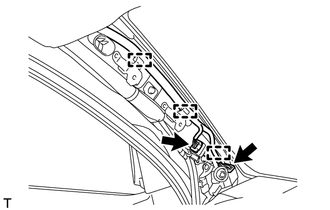
Disconnect the 2 connectors and detach the 3 clamps from the front pillar LH.
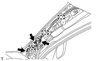
Remove the bolt.
Disconnect the 2 connectors and detach the 3 clamps from the front pillar RH.
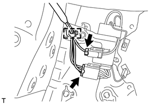
Disconnect the 2 connectors and detach the clamp from the rear pillar LH.
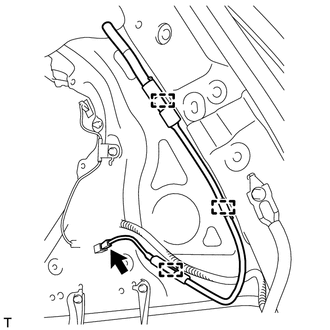
Disconnect the connector and detach the 3 clamps from the rear pillar RH.
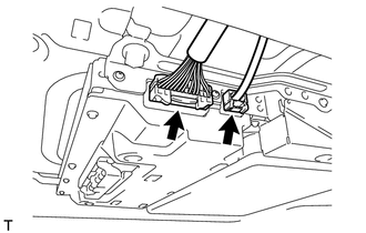
w/ Rear Seat Entertainment System:
Disconnect the 2 connectors.
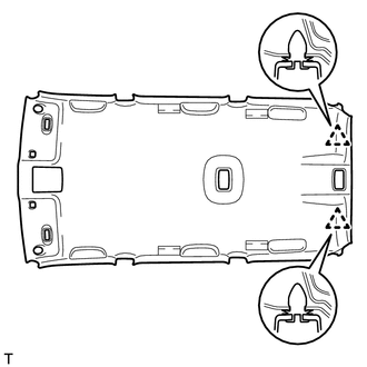
w/o Sliding Roof:
Detach the 2 clips.
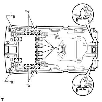
| *a | Guide |
| *b | Fastener |
w/ Sliding Roof:
Detach the 2 clips, 2 guides and 8 fasteners.
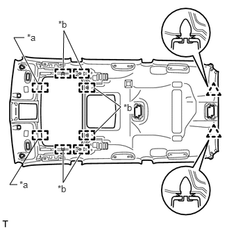
| *a | Guide |
| *b | Fastener |
w/ Rear Seat Entertainment System:
Detach the 2 clips, 2 guides and 6 fasteners.
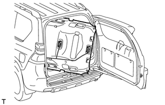
Remove the roof headlining assembly from the back door as shown in the illustration.
- NOTICE:
-
Be careful not to damage the roof headlining assembly when removing it.
73024
72.REMOVE FRONT SHOULDER BELT ANCHOR PLATE SUB-ASSEMBLY LH
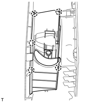
Detach the 5 claws of the front shoulder belt anchor plate sub-assembly LH and slide the front shoulder belt anchor plate sub-assembly LH in the direction of the arrow to remove it.
73023
73.REMOVE FRONT SHOULDER BELT ANCHOR PLATE SUB-ASSEMBLY RH
- HINT:
-
Use the same procedure described for the LH side.
73034
74.REMOVE REAR SHOULDER BELT ANCHOR PLATE SUB-ASSEMBLY LH
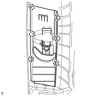
Detach the 6 claws of the rear shoulder belt anchor plate sub-assembly LH and slide the rear shoulder belt anchor plate sub-assembly LH in the direction of the arrow to remove it.
73033
75.REMOVE REAR SHOULDER BELT ANCHOR PLATE SUB-ASSEMBLY RH
- HINT:
-
Use the same procedure described for the LH side.
62432B
76.REMOVE NO. 1 ROOF SIDE RAIL GARNISH LH
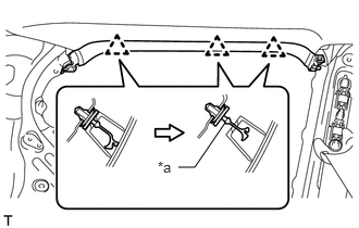
| *a | Cut Off Position |
Detach the 3 clips.
Cut off the 3 clips and remove the roof side rail garnish LH.
Remove 3 clips from the vehicle body.
62431B
77.REMOVE NO. 1 ROOF SIDE RAIL GARNISH RH
- HINT:
-
Use the same procedure described for the LH side.
62477A
78.REMOVE ROOF SIDE INNER GARNISH CAP LH (w/o Rear No. 2 Seat)
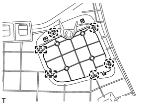
Detach the 4 claws and 2 guides and remove the roof side inner garnish cap LH.
62476A
79.REMOVE ROOF SIDE INNER GARNISH CAP RH (w/o Rear No. 2 Seat)
- HINT:
-
Use the same procedure described for the LH side.
73372
80.REMOVE REAR SEAT SHOULDER BELT HANGER LH
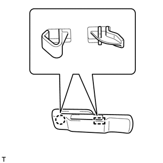
Detach the claw and guide and remove the rear seat shoulder belt hanger LH.
73371
81.REMOVE REAR SEAT SHOULDER BELT HANGER RH
- HINT:
-
Use the same procedure described for the LH side.
62627B
82.REMOVE QUARTER TRIM COVER
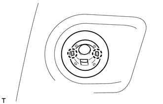
- HINT:
-
Use the same procedure for the other quarter trim cover.
Detach the 2 claws and remove the quarter trim cover.
64766B
83.REMOVE QUARTER TRIM JACK COVER
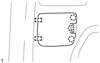
Detach the 3 claws and 2 guides and remove the quarter trim jack cover.
64715C
84.REMOVE DECK SIDE TRIM COVER LH
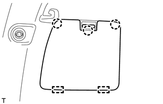
Detach the 3 claws and 2 guides and remove the deck side trim cover LH.
66424
85.REMOVE REAR SIDE RAIL SPACER LH (w/o Curtain Shield Airbag)
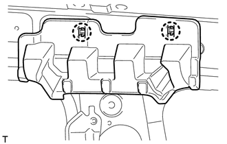
Detach the 2 claws and remove the rear side rail spacer LH.
66414A
86.REMOVE REAR SIDE RAIL SPACER RH (w/o Curtain Shield Airbag)
- HINT:
-
Use the same procedure described for the LH side.
66425A
87.REMOVE REAR NO. 2 SIDE RAIL SPACER LH (w/o Curtain Shield Airbag)
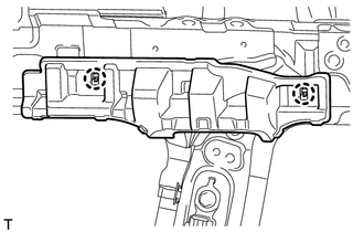
Detach the 2 claws and remove the rear No. 2 side rail spacer LH.
66415A
88.REMOVE REAR NO. 2 SIDE RAIL SPACER RH (w/o Curtain Shield Airbag)
- HINT:
-
Use the same procedure described for the LH side.
66426B
89.REMOVE REAR NO. 3 SIDE RAIL SPACER LH
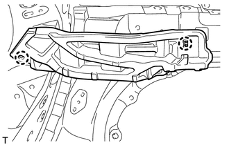
Detach the 2 claws and remove the rear No. 3 side rail spacer LH.
66416
90.REMOVE REAR NO. 3 SIDE RAIL SPACER RH
- HINT:
-
Use the same procedure described for the LH side.