REMOVAL
Removal / installation · Vehicles built Sep 2011 – Dec 2011
Versions by build date: Sep 2011 – Dec 2011 from Jan 2012
| 1.
REMOVE INTERCOOLER ASSEMBLY (w/ Intercooler) |
 |
(Click here)
| 2.
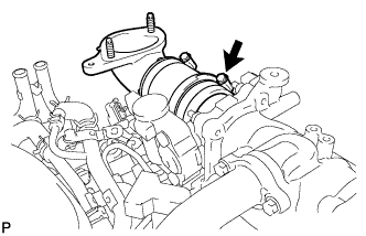
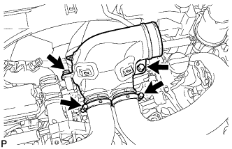
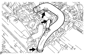
REMOVE NO. 1 COOL AIR INLET (w/o Intercooler)
|
|
- Loosen the No. 1 air hose clamp.
Disconnect the turbo pressure sensor connector, intake air temperature sensor connector and vacuum hose.
- Remove the 3 nuts, bolt and No. 1 cool air inlet.
Remove the gasket from the air tube RH.
| 3.
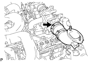
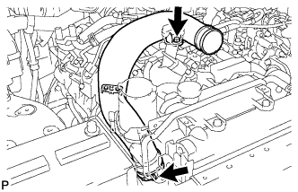
REMOVE NO. 2 COOL AIR INLET (w/o Intercooler)
|
|
- Loosen the No. 2 air hose clamp.
- Remove the 3 nuts, bolt and No. 2 cool air inlet.
Remove the gasket from the air tube LH.
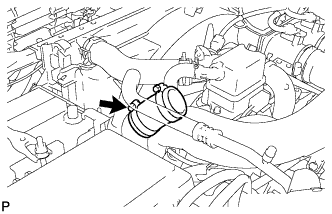
| 4.
REMOVE AIR TUBE SUB-ASSEMBLY RH
|
|
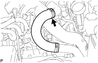
Loosen the hose clamp.
Remove the air tube from the throttle body.
| 5.
REMOVE AIR TUBE SUB-ASSEMBLY LH
|
|
Loosen the hose clamp.
Remove the air tube from the throttle body.
| 6.
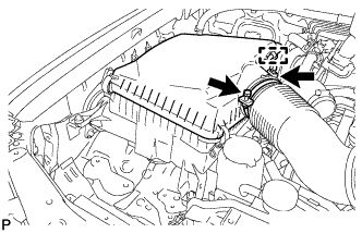
REMOVE AIR CLEANER CAP SUB-ASSEMBLY
|
|
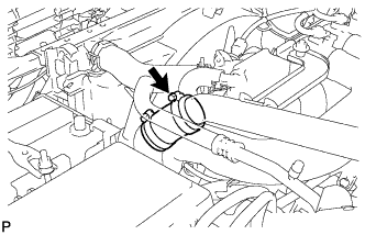
- Loosen the hose clamp.
Disconnect the mass air flow meter connector and using a clip remover, detach the wire harness clamp from the air cleaner cap.
Detach the 4 clamps and remove the air cleaner cap.
| 7.
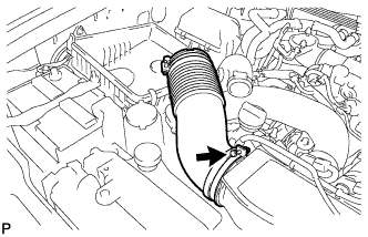
REMOVE NO. 1 AIR CLEANER HOSE
|
|
- Loosen the hose clamp and remove the No. 1 air cleaner hose.
| 8.
REMOVE INTAKE AIR CONNECTOR
|
|
- w/o Viscous Heater:
Disconnect the connector from the water temperature sensor.
Using a clip remover, detach the 3 wire harness clamps.
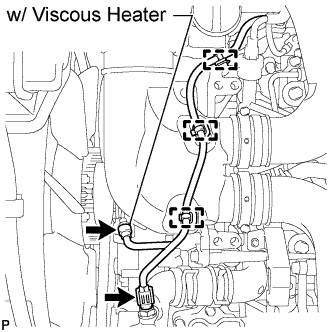
w/ Viscous Heater:
Disconnect the 2 connectors from the viscous with magnet clutch heater and water temperature sensor.
Using a clip remover, detach the 3 wire harness clamps.
- Loosen the 2 hose clamps and remove the 2 bolts and intake air connector.
| 9.
REMOVE NO. 1 AIR HOSE
|
|
- Loosen the hose clamp and remove the No. 1 air hose.
| 10.
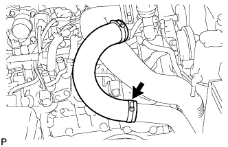
REMOVE NO. 2 AIR HOSE
|
|
- Loosen the hose clamp and remove the No. 2 air hose.
| 11.
REMOVE NO. 2 AIR CLEANER PIPE SUB-ASSEMBLY
|
|
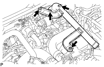
- Disconnect the ventilation hose from the oil separator.
Loosen the hose clamp.
Remove the bolt and No. 2 air cleaner pipe.
| 12.
REMOVE NO. 1 AIR CLEANER PIPE SUB-ASSEMBLY
|
|
- Loosen the hose clamp.
Remove the bolt and No. 1 air cleaner pipe.
| 13.
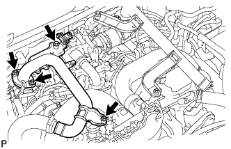
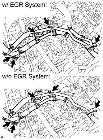
DISCONNECT NO. 4 WATER BY-PASS PIPE |
|
- w/ EGR System:
Detach the clamp and disconnect the connector.
- Remove the nut, 4 bolts and water by-pass pipe so that the glow plug can be removed in a step below.
| 14.
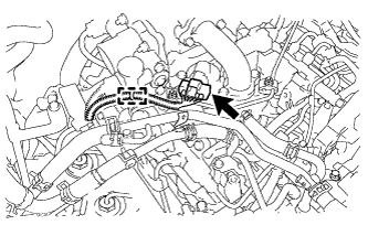
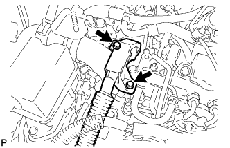
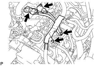
DISCONNECT ENGINE WIRE |
|
- Remove the 2 bolts and engine wire so that the glow plug can be removed in a step below.
- Disconnect the 2 connectors and remove the 2 bolts and engine wire so that the glow plug can be removed in a step below.
| 15.
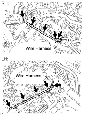
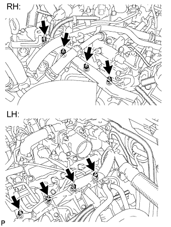
REMOVE NO. 1 GLOW PLUG CONNECTOR |
|
Remove the 2 screw grommets and 2 nuts, and disconnect the 2 wire harnesses.
Remove the 8 screw grommets, 8 nuts and 2 glow plug connectors.
| 16.
REMOVE GLOW PLUG ASSEMBLY |
|
- Using a 10 mm deep socket wrench, remove the 8 glow plugs.
- HINT:
- Before removing the glow plugs, thoroughly clean off all dirt, sand, etc.