2011-2013 Land Cruiser · Service Manual Engine / Hybrid / EV System

REMOVAL

Removal / installation · Vehicles built Sep 2011 – Dec 2011

Versions by build date: Sep 2011 – Dec 2011 from Jan 2012


1. REMOVE FRONT FENDER SPLASH SHIELD SUB-ASSEMBLY LH

  1. A174148
    Remove the 3 bolts and screw.

  1. Loosen the clip and remove the splash shield.


2. REMOVE FRONT FENDER SPLASH SHIELD SUB-ASSEMBLY RH

  1. A174148
    Remove the 3 bolts and screw.

  1. Loosen the clip and remove the splash shield.


3. REMOVE NO. 1 ENGINE UNDER COVER SUB-ASSEMBLY

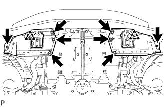
  1. A178461
    Remove the 10 bolts and under cover.


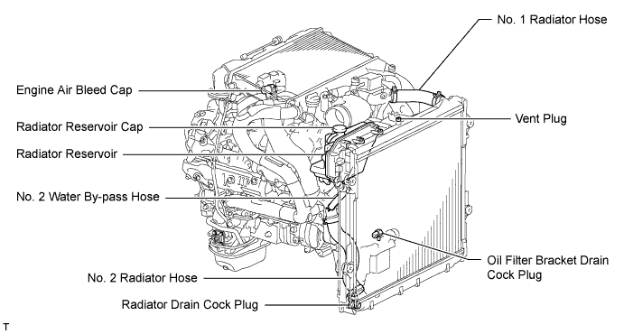
4. DRAIN ENGINE COOLANT

CAUTION:
Do not remove the radiator reservoir cap while the engine and radiator are still hot. Pressurized, hot engine coolant and steam may be released and cause serious burns.

HINT:
Collect the coolant in a container and dispose of it according to the regulations in your area.

  1. Loosen the radiator drain cock plug.

  1. Remove the radiator reservoir cap to drain the coolant in the radiator.

  1. Loosen the oil filter bracket drain cock plug to drain the coolant in the engine.

    A174741E01

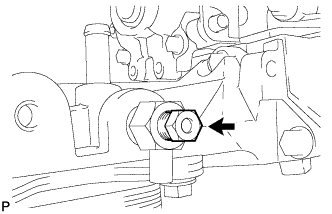
  1. Tighten the radiator drain cock plug by hand.

  1. A177208
    Tighten the oil filter bracket drain cock plug.

    Torque:
    13 N*m{ 133 kgf*cm , 10 ft.*lbf }


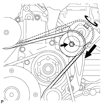
5. REMOVE V-RIBBED BELT (w/ Viscous Heater)

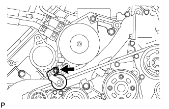
  1. A174847
    Loosen the lock nut and turn the bolt counterclockwise.

  1. Remove the V-ribbed belt.


6. REMOVE NO. 1 IDLER PULLEY (w/ Viscous Heater)

  1. A177430
    Remove the bolt, cover, No. 1 idler pulley and collar.


7. REMOVE NO. 3 IDLER PULLEY (w/ Viscous Heater)

  1. A177431
    Remove the nut and No. 3 idler pulley.


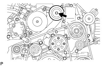
8. REMOVE V-RIBBED BELT

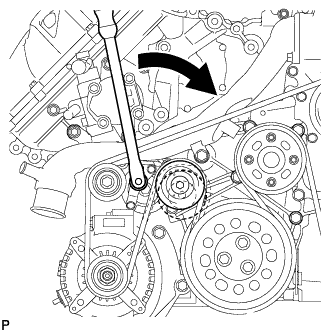
  1. A174849
    Using a wrench to the V-ribbed belt tensioner bracket, turn the wrench clockwise and remove the V-ribbed belt.

9. REMOVE INTERCOOLER ASSEMBLY (w/ Intercooler)
  1. Remove the intercooler assembly (Click here).


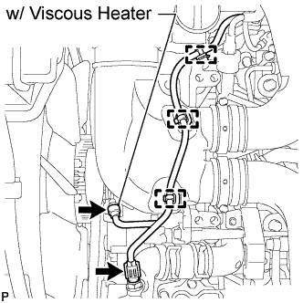
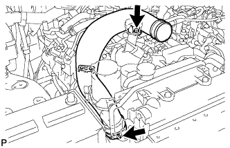
10. DISCONNECT WATER HOSE SUB-ASSEMBLY (w/ Viscous Heater)

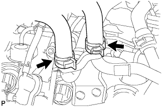
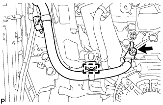
  1. A179014E01
    Disconnect the 2 water hoses.


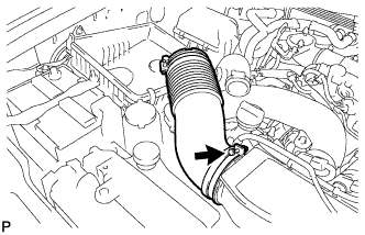
11. REMOVE AIR CLEANER CAP SUB-ASSEMBLY

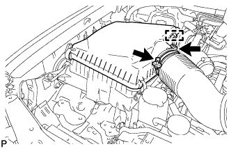
  1. A174698
    Loosen the hose clamp.

  1. Disconnect the mass air flow meter connector and using a clip remover, detach the wire harness clamp from the air cleaner cap.

  1. Detach the 4 clamps and remove the air cleaner cap.


12. REMOVE NO. 1 AIR CLEANER HOSE

  1. A174699
    Loosen the hose clamp and remove the No. 1 air cleaner hose.


13. REMOVE INTAKE AIR CONNECTOR

  1. A174749E01
    w/o Viscous Heater:

    1. Disconnect the connector from the water temperature sensor.

    2. Using a clip remover, detach the 3 wire harness clamps.

  1. w/ Viscous Heater:

    1. Disconnect the 2 connectors from the viscous with magnet clutch heater and water temperature sensor.

    2. Using a clip remover, detach the 3 wire harness clamps.

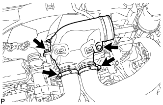
  1. A174710
    Loosen the 2 hose clamps and remove the 2 bolts and intake air connector.


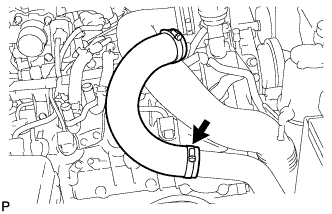
14. REMOVE NO. 1 AIR HOSE

  1. A177374
    Loosen the hose clamp and remove the No. 1 air hose.


15. REMOVE NO. 3 AIR TUBE

  1. A174751
    Disconnect the wire harness from the clamp.

  1. Remove the nut and ground wire.

  1. A174752
    Remove the bolt and disconnect the wire harness bracket.

  1. A174708
    Loosen the hose clamp and remove the bolt and No. 3 air tube.


16. REMOVE HEATER WATER PIPE SUB-ASSEMBLY (w/ Viscous Heater)

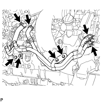
  1. A174689
    Remove the 4 bolts and disconnect the 4 water hose ends, and then remove the heater water pipe.


17. REMOVE NO. 1 AIR CLEANER PIPE SUB-ASSEMBLY

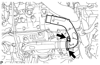
  1. A174714
    Loosen the hose clamp.

  1. Remove the bolt and No. 1 air cleaner pipe.


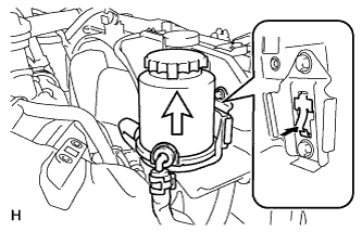
18. DISCONNECT VANE PUMP OIL RESERVOIR ASSEMBLY

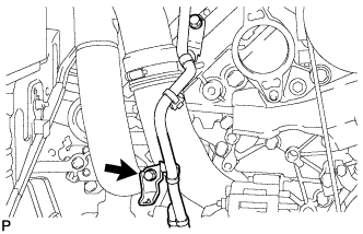
  1. A177428
    Insert a screwdriver between the reservoir and oil reservoir bracket, push the claw, and then disconnect the reservoir by pulling it upwards.


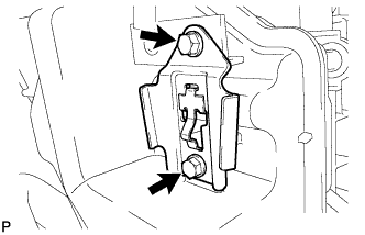
19. REMOVE NO. 1 OIL RESERVOIR BRACKET

  1. A184319
    Remove the 2 bolts and bracket.


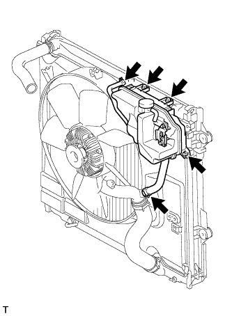
20. REMOVE RADIATOR RESERVOIR ASSEMBLY

  1. A174735
    Disconnect the 2 hoses.

  1. Remove the 3 bolts and radiator reservoir.


21. REMOVE POWER STEERING OIL PRESSURE SWITCH

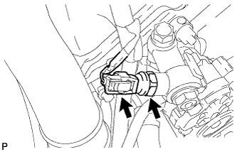
  1. A175768
    Disconnect the oil pressure switch connector.

  1. Using a 19 mm deep socket wrench, remove the oil pressure switch.

  1. Remove the O-ring from the oil pressure switch.

← ON-VEHICLE INSPECTION (from Jan 2012)REMOVAL (from Jan 2012) →