REMOVAL
Removal / installation · Vehicles built Sep 2011 – Dec 2011
Versions by build date: Sep 2011 – Dec 2011 from Jan 2012
| 1.
DISCONNECT CABLE FROM NEGATIVE BATTERY TERMINAL |
 |
- CAUTION:
- Wait at least 90 seconds after disconnecting the cable from the negative (-) battery terminal to disable the SRS system.
- NOTICE:
- When disconnecting the cable, some systems need to be initialized after the cable is reconnected (Click here).
Disconnect the cables from the negative (-) main battery and sub-battery terminals.
| 2.
REMOVE THERMOSTAT |
|
Remove the thermostat (Click here).
| 3.
REMOVE FUEL COOLER ASSEMBLY |
|
Remove the fuel cooler assembly (Click here).
| 4.
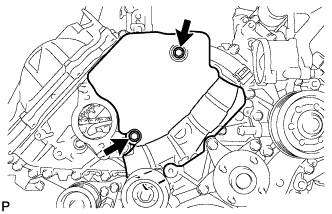
REMOVE TIMING GEAR COVER INSULATOR (w/ Intercooler)
|
|
- w/o Viscous Heater:
Remove the 2 bolts and timing gear cover insulator.
- w/ Viscous Heater:
Remove the timing gear cover insulator.
| 5.
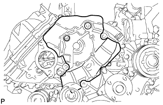
REMOVE TIMING CHAIN COVER PLATE |
|
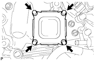
Remove the 4 bolts, cover plate and gasket.
| 6.
REMOVE NO. 1 FUEL PIPE |
|
- Remove the union bolt, fuel pipe and 2 gaskets.
| 7.
REMOVE FUEL SUPPLY PUMP |
|
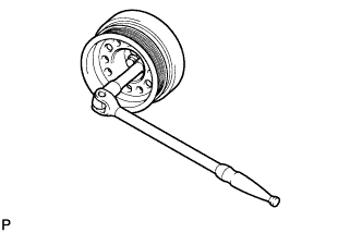
- Using a wrench, hold the crankshaft.
- NOTICE:
- Do not turn the crankshaft counterclockwise.
- If it is turned counterclockwise, check that the crankshaft pulley set bolt is not loose. If loose, tighten the bolt (Click here).
-
Torque:
- 108 N*m{
1101 kgf*cm
, 80 ft.*lbf
}
or more
- Remove the set nut.
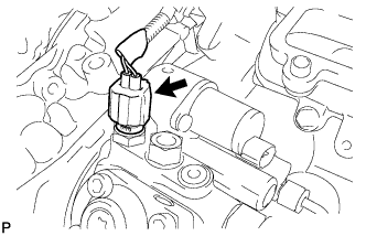
- Disconnect the fuel temperature sensor connector.
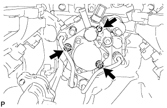
- Using a 6 mm hexagon wrench, remove the bolt.
Loosen the 2 nuts.
- Disconnect the pump from the supply pump drive gear.
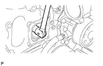
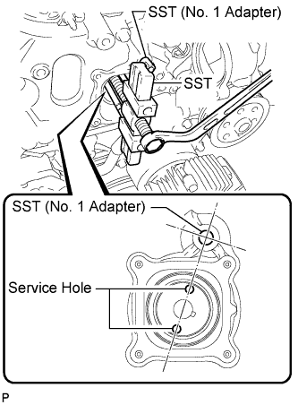
Install SST (No. 1 adapter) to the timing chain cover.
- SST
- 09950-50013
(09951-05010, 09952-05010, 09953-05020, 09954-05031, 09955-05010)
- NOTICE:
- Do not use any tools in this procedure.
Rotate the supply pump gear so that the service holes are aligned with SST (No. 1 adapter) as shown in the illustration.
Using SST, disconnect the pump from the supply pump drive gear.
- NOTICE:
- When removing or installing SST, do not push the supply pump gear.
- Apply lubricant to the threads and tip of SST (center bolt) before using it.
Remove the 2 nuts.
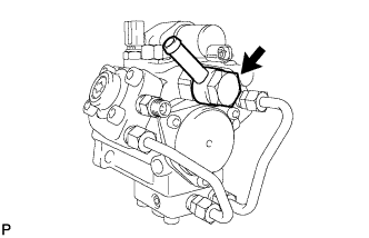
- NOTICE:
- Do not hold the supply pump by the parts indicated by the arrows in the illustration, as this may result in deformation, damage, and fuel leakage.
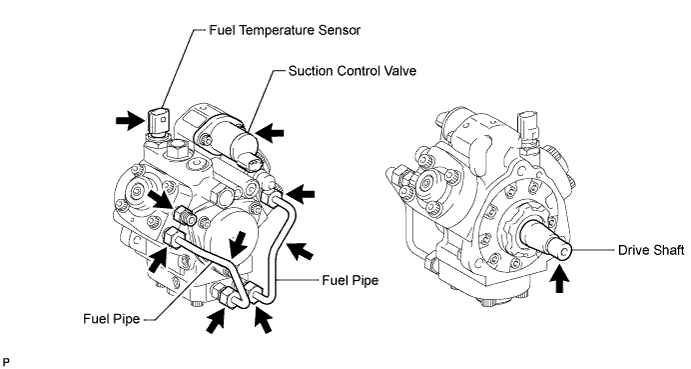

- The pump must be kept horizontal.
Remove the O-ring from the supply pump.