INSTALLATION
Removal / installation · Vehicles built from Jan 2012
Versions by build date: Sep 2011 – Dec 2011 from Jan 2012
| 1. INSTALL WINCH ASSEMBLY |

Using a crane or equivalent, install the winch assembly.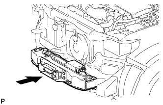

- CAUTION:
- Be careful as the winch assembly is very heavy.
Connect the wire with the nut.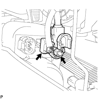
- Torque:
- 9.3 N*m{ 95 kgf*cm , 83 in.*lbf }
Connect the connector.
Move the cover in the direction indicated by the arrow shown in the illustration and attach the 2 claws.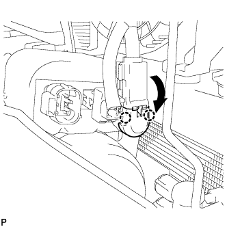
Install the mounting bracket with the 9 bolts.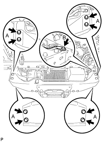
- Torque:
- for bolt A:
- 33 N*m{ 336 kgf*cm , 24 ft.*lbf }
- for bolt B:
- 19 N*m{ 194 kgf*cm , 15 ft.*lbf }
| 2. INSTALL WINCH CONTROL WIRE |
Install the winch control wire with the 2 nuts.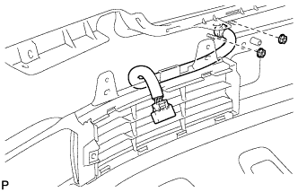
- Torque:
- 5 N*m{ 51 kgf*cm , 45 in.*lbf }
| 3. INSTALL TRANSMISSION OIL COOLER AIR DUCT (w/ Oil Cooler) |
Install the oil cooler air duct with the 4 bolts.
- Torque:
- 4.9 N*m{ 50 kgf*cm , 43 in.*lbf }
| 4. INSTALL RADIATOR SIDE DEFLECTOR RH (w/o Oil Cooler) |
Install the deflector with the 4 clips.
| 5. INSTALL RADIATOR SIDE DEFLECTOR LH |
Install the side deflector with the 4 clips.
| 6. INSTALL FRONT UPPER CENTER BUMPER RETAINER |
Install the front upper center bumper retainer with the 3 bolts.
| 7. INSTALL HEADLIGHT ASSEMBLY RH |
- HINT:
- Use the same procedure described for the LH side.
| 8. INSTALL HEADLIGHT ASSEMBLY LH |
for Halogen Headlight:
(Click here)
for HID Headlight:
(Click here)
| 9. INSTALL FRONT BUMPER EXTENSION RH |
- HINT:
- Use the same procedure described for the LH side.
| 10. INSTALL FRONT BUMPER EXTENSION LH |
Install the front bumper extension LH with the 3 bolts.
| 11. INSTALL FRONT BUMPER COVER |
w/ Fog Light:
Connect the No. 4 engine room wire connector.
Connect the winch control wire connector and attach the 10 claws to install the front bumper cover.
Install the 3 clips, 4 screws and 4 bolts.
Using a T30 "TORX" socket, install the 6 screws.
| 12. INSTALL RADIATOR GRILLE ASSEMBLY |
w/ Wide View Front Monitor System:
Connect the connector.
Attach the 2 clips and 8 claws to install the radiator grille assembly.
Install the 3 screws.
| 13. INSTALL FRONT BUMPER WINCH COVER SUB-ASSEMBLY |
Attach the 3 guides.
Attach the 2 claws and front bumper winch cover sub-assembly.
| 14. INSTALL UPPER RADIATOR SUPPORT SEAL |
| 15. INSTALL FRONT FENDER SPLASH SHIELD SUB-ASSEMBLY RH |
Push in the clip to install the front fender splash shield sub-assembly RH.
Install the 3 bolts and 2 screws.
| 16. INSTALL FRONT FENDER SPLASH SHIELD SUB-ASSEMBLY LH |
Push in the clip to install the front fender splash shield sub-assembly LH.
Install the 3 bolts and screw.
| 17. CONNECT CABLE TO NEGATIVE BATTERY TERMINAL |
- NOTICE:
- When disconnecting the cable, some systems need to be initialized after the cable is reconnected (Click here).