2011-2013 Land Cruiser · Service Manual Steering

INSTALLATION

Removal / installation · Vehicles built Sep 2011 – Dec 2011

Versions by build date: Sep 2011 – Dec 2011 from Jan 2012


1. CONNECT NO. 2 STEERING INTERMEDIATE SHAFT

  1. C172652E01
    Align the part of the dust cover labeled A with the No. 2 steering intermediate shaft, and install the No. 2 steering intermediate shaft assembly to the steering link assembly.

  1. Install the bolt.

    Torque:
    35 N*m{ 360 kgf*cm , 26 ft.*lbf }

    NOTICE:
    Be careful not to damage the dust cover.


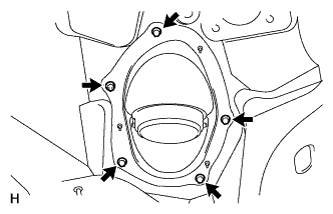
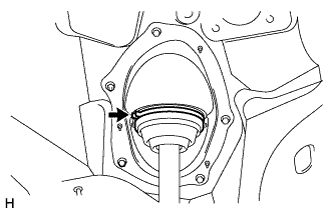
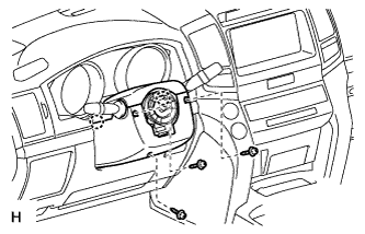
2. INSTALL STEERING COLUMN HOLE COVER SUB-ASSEMBLY

  1. C179099
    Install the 4 bolts and nut.

    Torque:
    5.0 N*m{ 51 kgf*cm , 44 in.*lbf }

    NOTICE:
    Do not fold back the boot part of the steering hole cover or extend it excessively. if it is extended excessively, return it to its original position.

    HINT:
    Install the steering intermediate shaft assembly from the inside of the vehicle.

  1. Install the clamp to the steering column hole cover.


3. CONNECT STEERING ACTUATOR ASSEMBLY
  1. Make sure that the power steering link assembly is centered.

  1. C179311E01
    Install the steering actuator assembly.

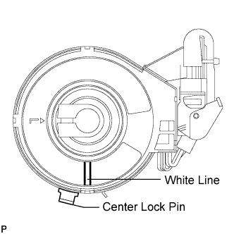
    1. If installing a new steering actuator assembly:
      Install the steering actuator assembly with the white paint on the upper surface of the spiral case facing down.

      NOTICE:
      Do not pull out the center lock pin.

    2. C179313E01
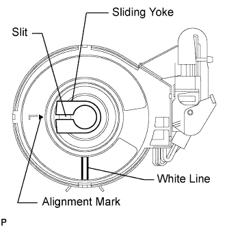
      If reinstalling the removed steering actuator assembly:
      1. Slowly turn the spiral case clockwise until it locks.
      2. Turn the spiral case two turns counterclockwise from the lock position.
      3. Align the slit of the sliding yoke with the alignment mark (▲).
      4. Install the steering actuator assembly with the white paint on the upper surface of the spiral case facing down.

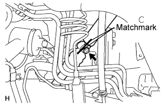
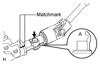
  1. C172649E01
    Align the matchmarks on the No. 2 steering intermediate shaft and steering actuator.

    NOTICE:
    1. Do not fold back the boot part of the steering hole cover or turn it excessively. If it is turned excessively, return it to its original position.
    2. Do not turn the actuator body and the spiral case.

    HINT:
    Install the steering actuator from the inside of the vehicle.

  1. Install the bolt.

    Torque:
    35 N*m{ 360 kgf*cm , 26 ft.*lbf }

  1. C180144
    Using needle nose pliers, lock the clamp to the steering column hole cover to install it.

    NOTICE:
    Be careful when performing the operation as the clamp may not lock if the claws of the clamp are deformed.

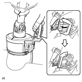
  1. C179338
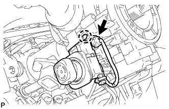
    Move the lock in the direction of the arrow and connect the steering actuator connector.

    HINT:
    When a new actuator is installed, remove the center lock pin.

  1. Connect the connector.


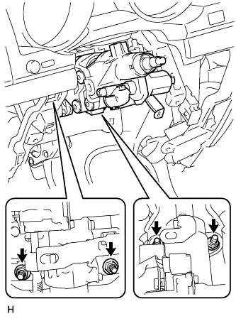
4. INSTALL STEERING COLUMN ASSEMBLY (TILT STEERING GEAR ASSEMBLY WITH MOTOR)

  1. C172653
    Install the 4 nuts and steering column.

    Torque:
    26 N*m{ 265 kgf*cm , 19 ft.*lbf }


5. INSTALL NO. 3 AIR DUCT SUB-ASSEMBLY
  1. Attach the 2 claws to install the duct.

  1. Install the clip.


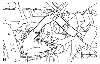
6. INSTALL WIRE HARNESS PROTECTOR AND WIRE HARNESS

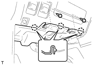
  1. C172657
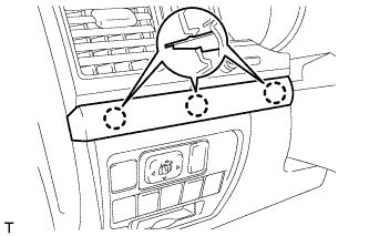
    Attach the 3 claws and install the wiring harness protector and wire harness.


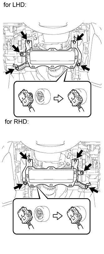
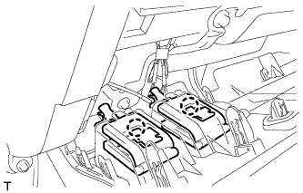
7. INSTALL DRIVER SIDE KNEE AIRBAG ASSEMBLY (w/ Driver Side Knee Airbag)

  1. B189604E01
    Connect the connector.

    NOTICE:
    When handling the airbag connector, take care not to damage the airbag wire harness.

  1. Install the driver side knee airbag with the 5 bolts.

    Torque:
    10 N*m{ 102 kgf*cm , 7 ft.*lbf }


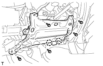
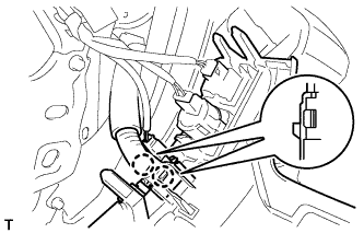
8. INSTALL LOWER INSTRUMENT PANEL SUB-ASSEMBLY (w/o Driver Side Knee Airbag)

B180299
  1. Attach the 2 claws and connect the DLC3.

  1. Install the lower instrument panel with the 5 bolts.


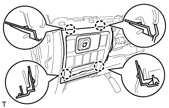
9. INSTALL NO.1 SWITCH HOLE BASE

B180298
  1. Connect the connectors.

  1. Attach the 4 claws to install the No. 1 switch hole base.


10. INSTALL LOWER NO. 1 INSTRUMENT PANEL FINISH PANEL
  1. Connect the connectors.

  1. B180296
    for Automatic Air Conditioning System:

    1. Attach the 2 claws to install the room temperature sensor.

  1. B181942
    Attach the 2 claws to connect the 2 control cables.

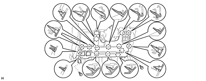
  1. w/ Driver Side Knee Airbag:

    1. Attach the 16 claws to install the lower No. 1 instrument panel finish panel.

    2. Install the 2 bolts.

      B291249

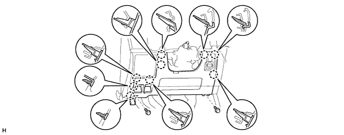
  1. w/o Driver Side Knee Airbag:

    1. Attach the 9 claws to install the lower No. 1 instrument panel finish panel.

    2. Install the 2 bolts.

      B291250

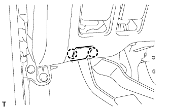
  1. B182569
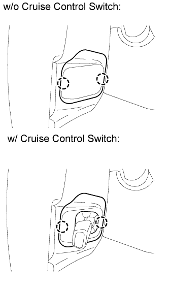
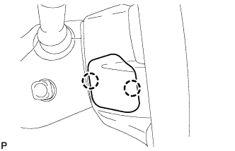
    Attach the 2 claws to close the hole cover.


11. INSTALL COWL SIDE TRIM BOARD LH

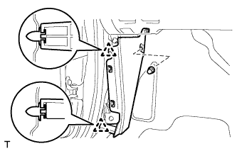
B181911
  1. Attach the 2 clips to install the cowl side trim board.

  1. Install the cap nut.


12. INSTALL NO. 1 INSTRUMENT PANEL UNDER COVER SUB-ASSEMBLY (w/ Floor Under Cover)

B182553
  1. Connect the connectors.

  1. Attach the 3 claws to install the No. 1 instrument panel under cover.

  1. Install the 2 screws.


13. INSTALL FRONT DOOR SCUFF PLATE LH

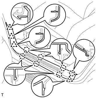
B181682
  1. Attach the 7 claws and 4 clips to install the scuff plate.


14. INSTALL INSTRUMENT CLUSTER FINISH PANEL SUB-ASSEMBLY (w/ Multi-information Display)

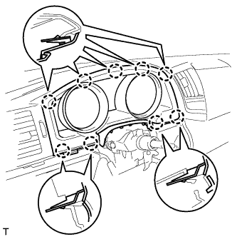
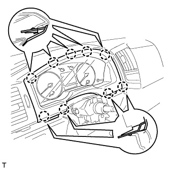
B180017
  1. Connect the connector.

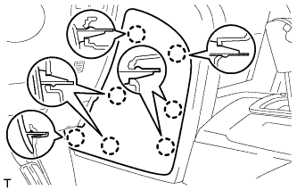
  1. Attach the 9 claws to install the instrument cluster finish panel.


15. INSTALL INSTRUMENT CLUSTER FINISH PANEL SUB-ASSEMBLY (w/o Multi-information Display)

B180016
  1. Attach the 9 claws to install the instrument cluster finish panel.


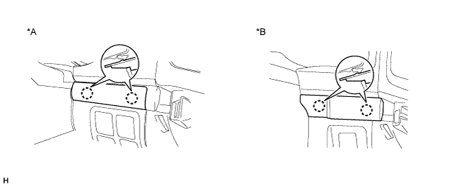
16. INSTALL NO. 2 INSTRUMENT CLUSTER FINISH PANEL GARNISH

  1. Attach the 2 claws to install the No. 2 instrument cluster finish panel garnish.

    B291252E01

    Text in Illustration 
    *A
    w/ Entry and Start System
    *B
    w/o Entry and Start System


17. INSTALL NO. 1 INSTRUMENT CLUSTER FINISH PANEL GARNISH

E155133
  1. Attach the 3 claws to install the No. 1 instrument cluster finish panel garnish.


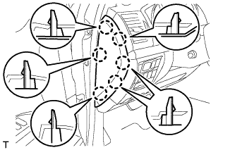
18. INSTALL INSTRUMENT SIDE PANEL LH

E155518
  1. Attach the 6 claws to install the instrument side panel.


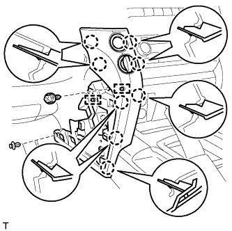
19. INSTALL LOWER INSTRUMENT PANEL PAD SUB-ASSEMBLY LH

  1. B181910
    Connect the connectors and 2 clamps.

  1. Attach the 8 claws to install the panel pad.

  1. Install the screw.

  1. Install the clip.


20. INSTALL NO. 2 INSTRUMENT PANEL FINISH PANEL CUSHION

  1. E155134
    Attach the 7 claws to install the panel cushion.


21. INSTALL COMBINATION SWITCH ASSEMBLY WITH SPIRAL CABLE SUB-ASSEMBLY

  1. C172677E01
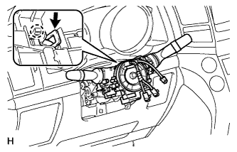
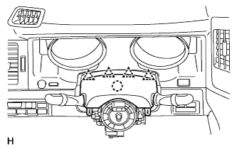
    Using pliers, grip the claws of the clamp and install the turn signal switch assembly with spiral cable sub-assembly to the steering column assembly with the clamp.

  1. C172676
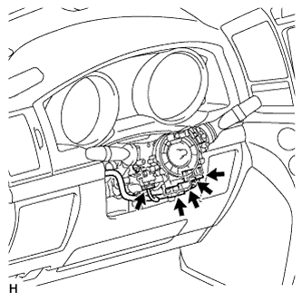
    Connect the 5 connectors to the turn signal switch with spiral cable.


22. INSTALL TILT AND TELESCOPIC SWITCH

  1. C159804
    Attach the claw to install the switch.

  1. Connect the switch connector.


23. INSTALL UPPER STEERING COLUMN COVER

  1. C172675
    Attach the claw to install the upper steering column cover.

  1. Attach the 4 clips to install the upper steering column cover onto the instrument cluster finish panel.


24. INSTALL LOWER STEERING COLUMN COVER

  1. C172674
    Attach the 2 claws to install the lower steering column cover.

    NOTICE:
    Do not damage the tilt and telescopic switch.

  1. Install the 3 screws.

    Torque:
    1.5 N*m{ 15 kgf*cm , 13 in.*lbf }


25. INSTALL STEERING WHEEL ASSEMBLY

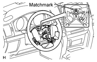
  1. C174823E01
    Align the matchmarks on the steering wheel assembly and steering main shaft assembly.

  1. Install the steering wheel assembly set nut.

    Torque:
    50 N*m{ 510 kgf*cm , 37 ft.*lbf }


26. INSTALL STEERING PAD

  1. B181568
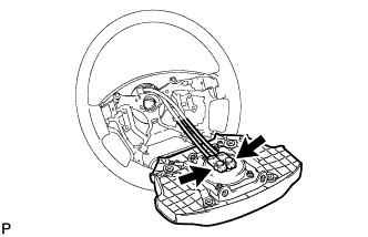
    Support the steering pad with one hand.

  1. Connect the 2 connectors to the steering pad.

    NOTICE:
    When handling the airbag connector, take care not to damage the airbag wire harness.

  1. Connect the horn connector.

  1. Confirm that the circumference groove of the "TORX" screw fits in the screw case, and place the steering pad onto the steering wheel.

  1. Using a T30 "TORX" socket wrench, tighten the 2 screws.

    Torque:
    8.8 N*m{ 90 kgf*cm , 78 in.*lbf }


27. INSTALL LOWER NO. 2 STEERING WHEEL COVER

  1. B189186E01
    Attach the 2 claws to install the cover.


28. INSTALL LOWER NO. 3 STEERING WHEEL COVER

  1. B181563
    Attach the 2 claws to install the cover.


29. CHECK FRONT WHEELS FACING STRAIGHT AHEAD

30. INSTALL FRONT WHEELS

31. CONNECT CABLE TO NEGATIVE BATTERY TERMINAL

NOTICE:
  1. Reset the AUTO TILT AWAY function setting to the previous condition by changing the customize parameter (Click here).
  2. When disconnecting the cable, some systems need to be initialized after the cable is reconnected (Click here).

32. INSPECT SRS WARNING LIGHT
  1. Inspect the SRS warning light (Click here).
← REASSEMBLY (from Sep 2011)INSTALLATION (from Jan 2012) →