After turning the engine switch off, waiting time may be required before disconnecting the cable from the battery terminal. Therefore, make sure to read the disconnecting the cable from the battery terminal notice before proceeding with work (Click here).
2.
DISCONNECT CABLE FROM NEGATIVE BATTERY TERMINAL
CAUTION:
Wait at least 90 seconds after disconnecting the cable from the negative (-) battery terminal to disable the SRS system.
NOTICE:
When disconnecting the cable, some systems need to be initialized after the cable is reconnected (Click here).
3.
REMOVE UPPER RADIATOR SUPPORT SEAL
Remove the 7 clips and upper radiator support seal.
4.
REMOVE FRONT FENDER APRON TRIM PACKING A
Remove the 3 clips and front fender apron seal front RH.
5.
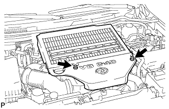
REMOVE NO. 1 ENGINE COVER SUB-ASSEMBLY
Remove the 2 nuts and No. 1 engine cover.
6.
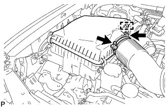
REMOVE AIR CLEANER CAP SUB-ASSEMBLY
Loosen the hose clamp.
Disconnect the mass air flow meter connector and using a clip remover, detach the wire harness clamp from the air cleaner cap.
Detach the 4 clamps and remove the air cleaner cap.
7.
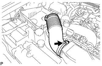
REMOVE NO. 1 AIR CLEANER HOSE
Loosen the hose clamp and remove the No. 1 air cleaner hose.
8.
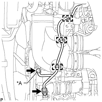
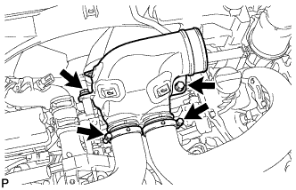
REMOVE INTAKE AIR CONNECTOR
w/ Viscous Heater: Disconnect the 2 connectors from the viscous with magnet clutch heater and water temperature sensor.
Text in Illustration
*A
w/ Viscous Heater
w/o Viscous Heater: Disconnect the connector from the water temperature sensor.
Using a clip remover, detach the 3 wire harness clamps.
Loosen the 2 hose clamps and remove the 2 bolts and intake air connector.
9.
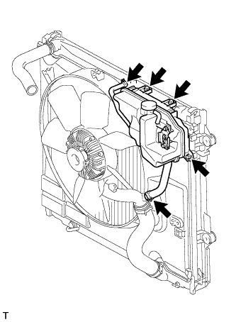
REMOVE RADIATOR RESERVOIR ASSEMBLY
Disconnect the 2 hoses.
Remove the 3 bolts and radiator reservoir.
10.
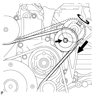
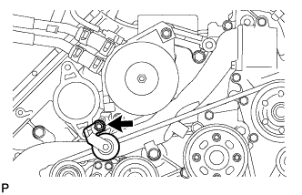
REMOVE V-RIBBED BELT (w/ Viscous Heater)
Loosen the lock nut and turn the bolt counterclockwise.
Remove the V-ribbed belt.
11.
REMOVE NO. 1 IDLER PULLEY (w/ Viscous Heater)
Remove the bolt, cover, No. 1 idler pulley and collar.
12.
REMOVE NO. 3 IDLER PULLEY (w/ Viscous Heater)
Remove the nut and No. 3 idler pulley.
13.
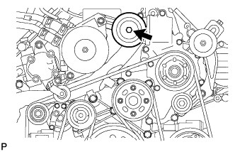
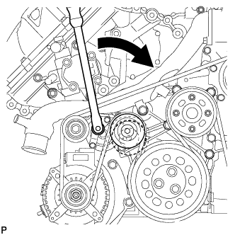
REMOVE V-RIBBED BELT
Using a wrench to the V-ribbed belt tensioner bracket, turn the wrench clockwise and remove the V-ribbed belt.
14.
DRAIN POWER STEERING FLUID
15.
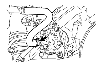
DISCONNECT NO. 1 OIL RESERVOIR TO PUMP HOSE
Slide the clip and disconnect the No. 1 oil reservoir to pump hose from the vane pump.
16.
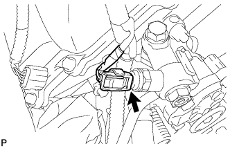
DISCONNECT POWER STEERING OIL PRESSURE SWITCH CONNECTOR
Disconnect the connector.
17.
REMOVE PRESSURE FEED TUBE ASSEMBLY
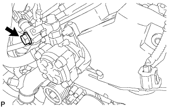
Remove the union bolt, union and disconnect the pressure feed tube.