Home › Engine / Hybrid System › 1GR-FE (ENGINE CONTROL) › SFI SYSTEM › 2015.08–2017.08
RM2660E _51 Engine / Hybrid System _052774 1GR-FE ENGINE CONTROL _0255001 SFI SYSTEM J

1GR-FE ENGINE CONTROL  SFI SYSTEM  VC Output Circuit  


DESCRIPTION

The ECM constantly generates 5 V power from the battery voltages supplied to the +B (BATT) terminal to operate the microprocessor. The ECM also provides this power to the sensors through the VC output circuit.
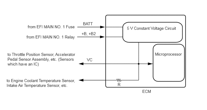
A256646E46
0.958,0.844 2.802,1.135 1.844,0.292 10 false from EFI MAIN NO. 1 Fuse 0.917,1.198 2.677,1.49 1.76,0.292 10 false from EFI MAIN NO. 1 Relay 0.26,1.802 2.708,2.417 2.448,0.615 10 false to Throttle Position Sensor, Accelerator Pedal Sensor Assembly, etc. (Sensors which have an IC) 0.229,2.708 2.656,3.271 2.427,0.563 10 false to Engine Coolant Temperature Sensor, Intake Air Temperature Sensor, etc. 4.927,3.083 5.333,3.448 0.406,0.365 10 false ECM 2.875,0.74 3.26,0.885 0.385,0.146 10 false BATT 2.823,1.083 3.448,1.292 0.625,0.208 10 false +B, +B2 3.01,1.99 3.292,2.177 0.281,0.188 10 false VC 4.396,0.896 6.188,1.25 1.792,0.354 10 false 5 V Constant Voltage Circuit 5.365,1.792 6.354,2.146 0.99,0.354 10 false Microprocessor 4.073,2.844 4.219,3.01 0.146,0.167 10 false R

When the VC circuit is short-circuited, the microprocessor in the ECM and sensors that are supplied with power through the VC circuit are inactivated because the power is not supplied from the VC circuit. Under this condition, the system does not start up and the MIL does not illuminate even if the system malfunctions.

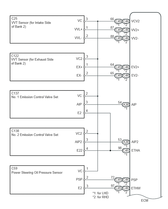
WIRING DIAGRAM

·

VC Output Circuit


U163735E01
0.488,0.7 0.809,0.845 0.320,0.145 10 C25 0.488,0.873 2.255,1.219 1.767,0.346 10 VVT Sensor (for Intake Side of Bank 2) 4.71,1.08 4.905,1.225 0.195,0.145 10 87 0.474,2.28 0.836,2.424 0.362,0.145 10 C122 0.474,2.441 2.351,2.767 1.877,0.326 10 VVT Sensor (for Exhaust Side of Bank 2) 0.485,3.875 0.857,4.019 0.372,0.145 10 C137 0.485,4.028 2.573,4.207 2.088,0.179 10 No. 1 Emission Control Valve Set 0.488,5.473 0.857,5.618 0.369,0.145 10 C138 0.488,5.64 2.579,5.819 2.091,0.179 10 No. 2 Emission Control Valve Set 0.488,7.066 0.809,7.210 0.320,0.145 10 C59 0.488,7.237 2.746,7.416 2.258,0.179 10 Power Steering Oil Pressure Sensor 3.663,3.884 3.776,4.028 0.113,0.145 10 2 4.731,7.453 4.926,7.598 0.195,0.145 10 72 4.731,7.802 4.926,7.947 0.195,0.145 10 97 5.037,4.263 5.218,4.407 0.181,0.145 10 54 5.035,5.845 5.216,5.990 0.181,0.145 10 53 4.71,3.025 4.905,3.170 0.195,0.145 10 65 4.708,2.652 4.903,2.796 0.195,0.145 10 64 4.71,1.455 4.905,1.600 0.195,0.145 10 88 4.71,0.724 4.905,0.869 0.195,0.145 10 66 3.669,1.08 3.782,1.225 0.113,0.145 10 1 3.665,0.724 3.778,0.869 0.113,0.145 10 3 3.663,4.615 3.776,4.759 0.113,0.145 10 4 3.663,4.253 3.776,4.397 0.113,0.145 10 3 3.676,3.017 3.789,3.162 0.113,0.145 10 2 3.674,2.658 3.787,2.803 0.113,0.145 10 1 3.676,2.317 3.789,2.462 0.113,0.145 10 3 3.676,1.435 3.789,1.580 0.113,0.145 10 2 3.309,0.794 3.557,0.956 0.248,0.162 10 VC 5.595,7.556 5.945,7.725 0.350,0.169 10 PSP 3.305,4.704 3.531,4.874 0.225,0.170 10 E2 3.268,4.344 3.521,4.502 0.253,0.158 10 AIP 3.301,3.982 3.544,4.138 0.244,0.156 10 VC 3.253,2.756 3.561,2.917 0.309,0.162 10 EX+ 3.244,2.402 3.554,2.565 0.310,0.163 10 VC2 3.177,1.154 3.564,1.304 0.387,0.150 10 VVL+ 5.597,1.186 5.975,1.340 0.378,0.155 10 VV2+ 5.602,1.541 5.960,1.714 0.358,0.173 10 VV2- 5.597,2.757 5.982,2.918 0.385,0.162 10 EV2+ 5.606,3.112 5.964,3.269 0.357,0.157 10 EV2- 3.187,1.523 3.538,1.726 0.350,0.203 10 VVL- 3.267,3.113 3.568,3.268 0.301,0.154 10 EX- 5.602,4.353 5.952,4.556 0.350,0.203 10 AIP 5.606,5.94 5.956,6.100 0.350,0.160 10 AIP2 5.595,7.905 6.066,8.069 0.471,0.164 10 ETHW 5.248,0.809 5.568,0.954 0.320,0.145 10 C46 5.248,1.177 5.568,1.322 0.320,0.145 10 C46 5.248,1.53 5.568,1.674 0.320,0.145 10 C46 5.244,7.546 5.565,7.691 0.320,0.145 10 C46 5.244,7.9 5.565,8.045 0.320,0.145 10 C46 5.25,5.942 5.570,6.087 0.320,0.145 10 A38 5.25,4.352 5.570,4.497 0.320,0.145 10 A38 5.6,0.815 6.010,0.959 0.411,0.145 10 VCV2 6.02,8.426 6.370,8.583 0.350,0.157 10 ECM 3.676,5.487 3.789,5.631 0.113,0.145 10 2 3.676,6.216 3.789,6.360 0.113,0.145 10 4 3.676,5.849 3.789,5.993 0.113,0.145 10 3 3.271,6.307 3.543,6.477 0.272,0.170 10 E22 3.197,5.94 3.533,6.099 0.336,0.158 10 AIP2 3.229,5.585 3.557,5.741 0.327,0.156 10 VC2 3.685,7.076 3.798,7.220 0.113,0.145 10 1 3.685,7.808 3.799,7.952 0.113,0.145 10 3 3.685,7.445 3.798,7.589 0.113,0.145 10 2 3.328,7.897 3.553,8.067 0.225,0.170 10 E2 3.243,7.536 3.543,7.694 0.299,0.158 10 PSP 3.323,7.174 3.567,7.330 0.244,0.156 10 VC 4.927,0.808 5.247,0.952 0.320,0.145 10 C45 4.927,1.176 5.247,1.321 0.320,0.145 10 C45 4.927,1.529 5.247,1.673 0.320,0.145 10 C45 4.97,0.974 5.130,1.123 0.159,0.149 10 *1 5.299,0.974 5.459,1.123 0.159,0.149 10 *2 4.97,1.339 5.130,1.488 0.159,0.149 10 *1 5.299,1.343 5.459,1.492 0.159,0.149 10 *2 4.97,1.694 5.130,1.843 0.159,0.149 10 *1 4.923,2.756 5.243,2.901 0.320,0.145 10 C45 4.927,3.119 5.247,3.264 0.320,0.145 10 C45 4.968,2.927 5.127,3.076 0.159,0.149 10 *1 5.299,1.694 5.459,1.843 0.159,0.149 10 *2 5.246,2.756 5.566,2.901 0.320,0.145 10 C46 5.248,3.118 5.568,3.262 0.320,0.145 10 C46 5.297,2.926 5.457,3.075 0.159,0.149 10 *2 4.97,3.293 5.130,3.442 0.159,0.149 10 *1 5.306,4.522 5.466,4.671 0.159,0.149 10 *1 5.306,6.111 5.466,6.260 0.159,0.149 10 *1 5.037,6.201 5.218,6.346 0.181,0.145 10 98 5.606,6.304 6.012,6.464 0.406,0.160 10 ETHA 5.242,6.304 5.562,6.448 0.320,0.145 10 C45 5.306,6.48 5.466,6.628 0.159,0.149 10 *1 5.299,3.293 5.459,3.442 0.159,0.149 10 *2 4.97,7.711 5.130,7.860 0.159,0.149 10 *1 5.299,7.711 5.459,7.860 0.159,0.149 10 *2 4.97,8.073 5.130,8.222 0.159,0.149 10 *1 5.3,8.073 5.459,8.222 0.159,0.149 10 *2 4.923,7.546 5.243,7.691 0.320,0.145 10 C45 4.923,7.9 5.243,8.045 0.320,0.145 10 C45 3.95,8.118 4.708,8.450 0.758,0.332 10 *1: for LHD *2: for RHD

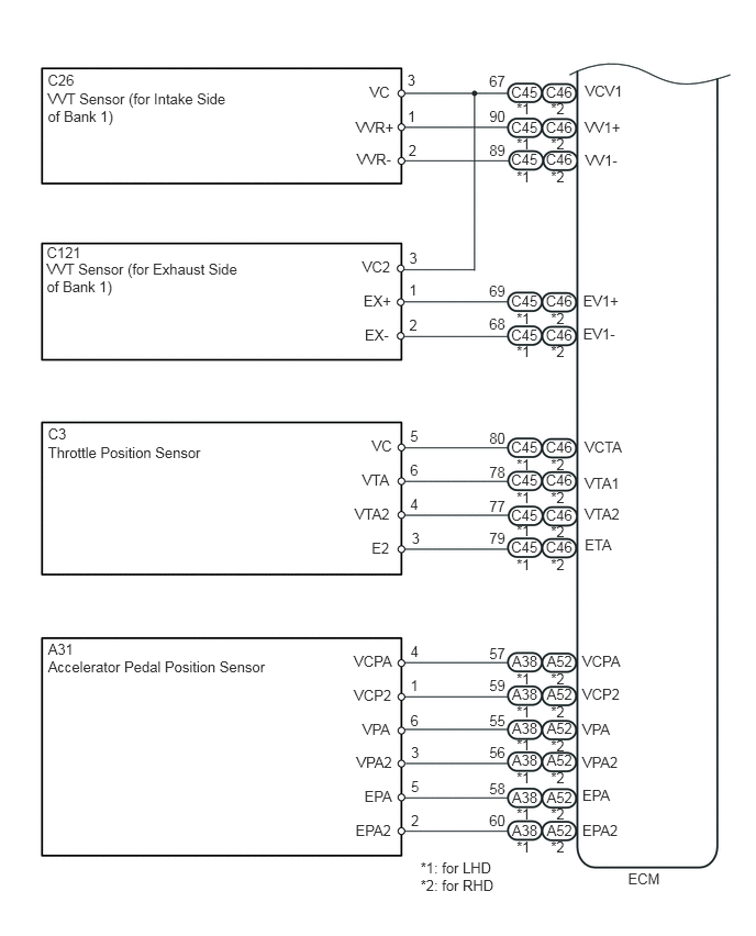
U163502E01
0.453,0.678 0.773,0.822 0.320,0.145 10 C26 0.453,0.851 2.208,1.179 1.755,0.329 10 VVT Sensor (for Intake Side of Bank 1) 0.443,2.31 0.812,2.454 0.369,0.145 10 C121 0.443,2.469 2.321,2.801 1.878,0.332 10 VVT Sensor (for Exhaust Side of Bank 1) 0.455,4.036 0.775,4.181 0.320,0.145 10 C3 0.455,4.209 1.985,4.388 1.531,0.179 10 Throttle Position Sensor 0.455,6.072 0.775,6.216 0.320,0.145 10 A31 0.455,6.241 2.611,6.420 2.156,0.179 10 Accelerator Pedal Position Sensor 3.888,4.049 4.002,4.194 0.113,0.145 10 5 4.638,0.69 4.833,0.834 0.195,0.145 10 67 3.865,1.026 3.978,1.170 0.113,0.145 10 1 3.861,0.675 3.974,0.820 0.113,0.145 10 3 3.888,4.703 4.002,4.847 0.113,0.145 10 4 3.888,4.376 4.002,4.521 0.113,0.145 10 6 3.879,2.998 3.992,3.142 0.113,0.145 10 2 3.879,2.671 3.992,2.815 0.113,0.145 10 1 3.879,2.36 3.992,2.504 0.113,0.145 10 3 3.872,1.345 3.985,1.490 0.113,0.145 10 2 3.505,0.794 3.753,0.955 0.248,0.162 10 VC 3.363,4.792 3.755,4.962 0.392,0.170 10 VTA2 3.435,4.468 3.758,4.626 0.323,0.158 10 VTA 3.526,4.148 3.770,4.304 0.244,0.156 10 VC 3.446,2.768 3.755,2.930 0.309,0.162 10 EX+ 3.435,2.444 3.745,2.608 0.310,0.163 10 VC2 3.373,1.128 3.760,1.278 0.387,0.150 10 VVR+ 5.544,1.12 5.922,1.274 0.378,0.155 10 VV1+ 5.549,1.438 5.907,1.612 0.358,0.173 10 VV1- 5.527,2.766 5.912,2.928 0.385,0.162 10 EV1+ 5.527,3.079 5.884,3.236 0.357,0.157 10 EV1- 3.383,1.425 3.734,1.628 0.350,0.203 10 VVR- 3.458,3.094 3.760,3.248 0.301,0.154 10 EX- 5.543,4.153 5.949,4.356 0.406,0.203 10 VCTA 5.543,4.498 5.949,4.658 0.406,0.160 10 VTA1 5.543,4.791 5.956,4.945 0.413,0.154 10 VTA2 4.638,1.022 4.833,1.167 0.195,0.145 10 90 4.638,1.34 4.833,1.484 0.195,0.145 10 89 4.638,2.677 4.833,2.821 0.195,0.145 10 69 4.638,2.994 4.833,3.139 0.195,0.145 10 68 4.638,4.069 4.833,4.214 0.195,0.145 10 80 4.638,4.395 4.833,4.539 0.195,0.145 10 78 4.638,4.719 4.833,4.864 0.195,0.145 10 77 4.638,5.023 4.833,5.167 0.195,0.145 10 79 4.638,6.113 4.833,6.257 0.195,0.145 10 57 4.638,6.421 4.833,6.566 0.195,0.145 10 59 4.638,6.75 4.833,6.895 0.195,0.145 10 55 4.638,7.051 4.833,7.196 0.195,0.145 10 56 4.638,7.395 4.833,7.539 0.195,0.145 10 58 4.638,7.703 4.833,7.848 0.195,0.145 10 60 5.547,0.781 5.957,0.925 0.411,0.145 10 VCV1 5.953,8.25 6.303,8.453 0.350,0.203 10 ECM 3.891,6.091 4.004,6.236 0.113,0.145 10 4 3.891,6.745 4.004,6.889 0.113,0.145 10 6 3.891,6.418 4.004,6.562 0.113,0.145 10 1 3.436,6.834 3.764,7.004 0.327,0.170 10 VPA 3.356,6.51 3.748,6.668 0.392,0.158 10 VCP2 3.355,6.19 3.751,6.345 0.397,0.156 10 VCPA 3.896,7.048 4.009,7.193 0.113,0.145 10 3 3.896,7.702 4.009,7.847 0.113,0.145 10 2 3.896,7.375 4.009,7.520 0.113,0.145 10 5 3.37,7.791 3.762,7.961 0.392,0.170 10 EPA2 3.454,7.467 3.753,7.625 0.299,0.158 10 EPA 3.379,7.147 3.776,7.303 0.397,0.156 10 VPA2 5.543,5.085 5.872,5.239 0.330,0.154 10 ETA 3.902,5.025 4.016,5.170 0.113,0.145 10 3 3.523,5.114 3.748,5.284 0.225,0.170 10 E2 5.52,6.83 5.847,6.999 0.327,0.170 10 VPA 5.52,6.505 5.912,6.663 0.392,0.158 10 VCP2 5.52,6.185 5.917,6.341 0.397,0.156 10 VCPA 5.52,7.787 5.912,7.957 0.392,0.170 10 EPA2 5.52,7.463 5.820,7.621 0.299,0.158 10 EPA 5.52,7.143 5.917,7.298 0.397,0.156 10 VPA2 4.846,0.787 5.126,0.936 0.281,0.149 10 C45 5.175,0.787 5.456,0.936 0.281,0.149 10 C46 4.897,0.949 5.063,1.098 0.166,0.149 10 *1 5.222,0.949 5.389,1.098 0.166,0.149 10 *2 4.846,1.12 5.126,1.269 0.281,0.149 10 C45 5.175,1.12 5.456,1.269 0.281,0.149 10 C46 4.897,1.278 5.063,1.427 0.166,0.149 10 *1 5.222,1.278 5.389,1.427 0.166,0.149 10 *2 4.846,1.428 5.126,1.577 0.281,0.149 10 C45 5.175,1.428 5.456,1.577 0.281,0.149 10 C46 4.897,1.59 5.063,1.739 0.166,0.149 10 *1 5.222,1.59 5.389,1.739 0.166,0.149 10 *2 4.846,2.773 5.126,2.922 0.281,0.149 10 C45 5.175,2.773 5.456,2.922 0.281,0.149 10 C46 4.897,2.935 5.063,3.084 0.166,0.149 10 *1 5.222,2.935 5.389,3.084 0.166,0.149 10 *2 4.846,3.092 5.126,3.241 0.281,0.149 10 C45 5.175,3.092 5.456,3.241 0.281,0.149 10 C46 4.897,3.254 5.063,3.403 0.166,0.149 10 *1 5.222,3.254 5.389,3.403 0.166,0.149 10 *2 4.846,4.157 5.126,4.306 0.281,0.149 10 C45 5.175,4.157 5.456,4.306 0.281,0.149 10 C46 4.897,4.319 5.063,4.468 0.166,0.149 10 *1 5.222,4.319 5.389,4.468 0.166,0.149 10 *2 4.846,4.472 5.126,4.621 0.281,0.149 10 C45 5.175,4.472 5.456,4.621 0.281,0.149 10 C46 4.897,4.634 5.063,4.783 0.166,0.149 10 *1 5.222,4.634 5.389,4.783 0.166,0.149 10 *2 4.846,4.805 5.126,4.954 0.281,0.149 10 C45 5.175,4.805 5.456,4.954 0.281,0.149 10 C46 4.897,4.951 5.063,5.100 0.166,0.149 10 *1 5.222,4.955 5.389,5.104 0.166,0.149 10 *2 4.846,5.106 5.126,5.255 0.281,0.149 10 C45 5.175,5.106 5.456,5.255 0.281,0.149 10 C46 4.897,5.268 5.063,5.417 0.166,0.149 10 *1 5.222,5.268 5.389,5.417 0.166,0.149 10 *2 4.853,6.189 5.134,6.338 0.281,0.149 10 A38 5.183,6.189 5.464,6.338 0.281,0.149 10 A52 4.853,6.495 5.134,6.644 0.281,0.149 10 A38 5.183,6.495 5.464,6.644 0.281,0.149 10 A52 4.853,6.827 5.134,6.976 0.281,0.149 10 A38 5.183,6.827 5.464,6.976 0.281,0.149 10 A52 4.853,7.13 5.134,7.279 0.281,0.149 10 A38 5.183,7.13 5.464,7.279 0.281,0.149 10 A52 4.853,7.476 5.134,7.625 0.281,0.149 10 A38 5.183,7.476 5.464,7.625 0.281,0.149 10 A52 4.853,7.789 5.134,7.938 0.281,0.149 10 A38 5.183,7.789 5.464,7.938 0.281,0.149 10 A52 4.897,6.351 5.063,6.500 0.166,0.149 10 *1 5.222,6.351 5.389,6.500 0.166,0.149 10 *2 4.897,6.667 5.063,6.816 0.166,0.149 10 *1 5.222,6.667 5.389,6.816 0.166,0.149 10 *2 4.897,6.979 5.063,7.128 0.166,0.149 10 *1 5.222,6.985 5.389,7.134 0.166,0.149 10 *2 4.897,7.292 5.063,7.441 0.166,0.149 10 *1 5.222,7.292 5.389,7.441 0.166,0.149 10 *2 4.897,7.634 5.063,7.783 0.166,0.149 10 *1 5.222,7.634 5.389,7.783 0.166,0.149 10 *2 4.897,7.951 5.063,8.100 0.166,0.149 10 *1 5.222,7.951 5.389,8.100 0.166,0.149 10 *2 3.986,8.144 4.746,8.466 0.760,0.323 10 *1: for LHD *2: for RHD

CAUTION / NOTICE / HINT

NOTICE:

Inspect the fuses for circuits related to this system before performing the following inspection procedure.


PROCEDURE

1.READ VALUE USING GTS
a.

Connect the GTS to the DLC3.


b.

Turn the ignition switch to ON and GTS on.


c.

Check the communication between the GTS and ECM.

HINT:

It can be checked using the "Engine and ECT" item of the Data List.


Result
Result Proceed to
Communication is not possible A
Communication is possible B


A

2.CHECK TERMINAL VOLTAGE (POWER SOURCE OF ECM)

B

PROCEED TO NEXT SUSPECTED AREA SHOWN IN PROBLEM SYMPTOMS TABLE

2.CHECK TERMINAL VOLTAGE (POWER SOURCE OF ECM)
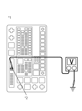
a.
A351229E01
0.34,0.658 0.634,0.865 0.295,0.207 10 *1 1.033,4.039 1.328,4.245 0.295,0.207 10 *2 0.483,2.824 1.107,4.004 false

Turn the ignition switch to ON.


b.

Measure the voltage according to the value(s) in the table below.

Standard Voltage:
Tester Connection Condition Specified Condition
1 (EFI No. 2 fuse) - Body ground Ignition switch ON 11 to 14 V


Text Illustration
*1 Engine Room Relay Block
*2 EFI No. 2 Fuse

HINT:

If the result is not as specified, since current is not flowing to the +B and +B2 terminals of the ECM, the system may not be started.


OK

3.CHECK MIL (THROTTLE POSITION SENSOR)

NG

3.CHECK MIL (THROTTLE POSITION SENSOR)
a.

Disconnect the throttle body with motor connector.


b.

Turn the ignition switch to ON.


c.

Turn the GTS on.


d.

Check the communication between the GTS and ECM.

HINT:

It can be checked using the "Engine and ECT" item of the Data List.


Result
Result Proceed to
Communication is not possible A
Communication is possible B


A

4.CHECK MIL (ACCELERATOR PEDAL POSITION SENSOR)

B

REPLACE THROTTLE BODY WITH MOTOR ASSEMBLY

4.CHECK MIL (ACCELERATOR PEDAL POSITION SENSOR)
a.

Disconnect the accelerator pedal position sensor connector.


b.

Turn the ignition switch to ON.


c.

Turn the GTS on.


d.

Check the communication between the GTS and ECM.

HINT:

It can be checked using the "Engine and ECT" item of the Data List.


Result
Result Proceed to
Communication is not possible A
Communication is possible B


A

5.CHECK MIL (NO. 1 EMISSION CONTROL VALVE SET)

B

REPLACE ACCELERATOR PEDAL POSITION SENSOR

5.CHECK MIL (NO. 1 EMISSION CONTROL VALVE SET)
a.

Disconnect the No. 1 emission control valve set connector.


b.

Turn the ignition switch to ON.


c.

Turn the GTS on.


d.

Check the communication between the GTS and ECM.

HINT:

It can be checked using the "Engine and ECT" item of the Data List.


Result
Result Proceed to
Communication is not possible A
Communication is possible B


A

6.CHECK MIL (NO. 2 EMISSION CONTROL VALVE SET)

B

6.CHECK MIL (NO. 2 EMISSION CONTROL VALVE SET)
a.

Disconnect the No. 2 emission control valve set connector.


b.

Turn the ignition switch to ON.


c.

Turn the GTS on.


d.

Check the communication between the GTS and ECM.

HINT:

It can be checked using the "Engine and ECT" item of the Data List.


Result
Result Proceed to
Communication is not possible A
Communication is possible B


A

7.CHECK MIL (POWER STEERING OIL PRESSURE SENSOR)

B

7.CHECK MIL (POWER STEERING OIL PRESSURE SENSOR)
a.

Disconnect the power steering oil pressure sensor connector.


b.

Turn the ignition switch to ON.


c.

Turn the GTS on.


d.

Check the communication between the GTS and ECM.

HINT:

It can be checked using the "Engine and ECT" item of the Data List.


Result
Result Proceed to
Communication is not possible A
Communication is possible B


A

8.CHECK MIL (VVT SENSOR for Intake Side of Bank 1)

B

8.CHECK MIL (VVT SENSOR for Intake Side of Bank 1)
a.

Disconnect the VVT sensor (for Intake Side of Bank 1) connector.


b.

Turn the ignition switch to ON.


c.

Turn the GTS on.


d.

Check the communication between the GTS and ECM.

HINT:

It can be checked using the "Engine and ECT" item of the Data List.


Result
Result Proceed to
Communication is not possible A
Communication is possible B


A

9.CHECK MIL (VVT SENSOR for Exhaust Side of Bank 1)

B

REPLACE VVT SENSOR (for Intake Side of Bank 1)

9.CHECK MIL (VVT SENSOR for Exhaust Side of Bank 1)
a.

Disconnect the VVT sensor (for Exhaust Side of Bank 1) connector.


b.

Turn the ignition switch to ON.


c.

Turn the GTS on.


d.

Check the communication between the GTS and ECM.

HINT:

It can be checked using the "Engine and ECT" item of the Data List.


Result
Result Proceed to
Communication is not possible A
Communication is possible B


A

10.CHECK MIL (VVT SENSOR for Intake Side of Bank 2)

B

REPLACE VVT SENSOR (for Exhaust Side of Bank 1)

10.CHECK MIL (VVT SENSOR for Intake Side of Bank 2)
a.

Disconnect the VVT sensor (for Intake Side of Bank 2) connector.


b.

Turn the ignition switch to ON.


c.

Turn the GTS on.


d.

Check the communication between the GTS and ECM.

HINT:

It can be checked using the "Engine and ECT" item of the Data List.


Result
Result Proceed to
Communication is not possible A
Communication is possible B


A

11.CHECK MIL (VVT SENSOR for Exhaust Side of Bank 2)

B

REPLACE VVT SENSOR (for Intake Side of Bank 2)

11.CHECK MIL (VVT SENSOR for Exhaust Side of Bank 2)
a.

Disconnect the VVT sensor (for Exhaust Side of Bank 2) connector.


b.

Turn the ignition switch to ON.


c.

Turn the GTS on.


d.

Check the communication between the GTS and ECM.

HINT:

It can be checked using the "Engine and ECT" item of the Data List.


Result
Result Proceed to
Communication is not possible A
Communication is possible B


A

12.CHECK HARNESS AND CONNECTOR

B

REPLACE VVT SENSOR (for Exhaust Side of Bank 2)

12.CHECK HARNESS AND CONNECTOR
a.

Disconnect the throttle body connector.


b.

Disconnect the accelerator pedal position sensor connector.


c.

Disconnect the air switching valve (for Bank 1) connector.


d.

Disconnect the air switching valve (for Bank 2) connector.


e.

Disconnect the power steering oil pressure sensor connector.


f.

Disconnect the VVT sensor (for Intake Side of Bank 1) connector.


g.

Disconnect the VVT sensor (for Exhaust Side of Bank 1) connector.


h.

Disconnect the VVT sensor (for Intake Side of Bank 2) connector.


i.

Disconnect the VVT sensor (for Exhaust Side of Bank 2) connector.


j.

Disconnect the ECM connectors.


k.

Disconnect the No. 1 integration relay connectors.


l.

Measure the resistance according to the value(s) in the table below.

Standard Resistance:
for LHD
Tester Connection Condition Specified Condition
C45-80 (VCTA) - Body ground Always 10 kΩ or higher
A38-57 (VCPA) - Body ground Always 10 kΩ or higher
A38-59 (VCP2) - Body ground Always 10 kΩ or higher
C45-67 (VCV1) - Body ground Always 10 kΩ or higher
C45-66 (VCV2) - Body ground Always 10 kΩ or higher
1S-11 - A38-3 (+B) Always Below 1 Ω
1S-11 - A38-2 (+B2) Always Below 1 Ω
1S-11 or A38-3 (+B) - Body ground Always 10 kΩ or higher
1S-11 or A38-2 (+B2) - Body ground Always 10 kΩ or higher

for RHD
Tester Connection Condition Specified Condition
C46-80 (VCTA) - Body ground Always 10 kΩ or higher
A52-57 (VCPA) - Body ground Always 10 kΩ or higher
A52-59 (VCP2) - Body ground Always 10 kΩ or higher
C46-67 (VCV1) - Body ground Always 10 kΩ or higher
C46-66 (VCV2) - Body ground Always 10 kΩ or higher
1S-11 - A52-3 (+B) Always Below 1 Ω
1S-11 - A52-2 (+B2) Always Below 1 Ω
1S-11 or A52-3 (+B) - Body ground Always 10 kΩ or higher
1S-11 or A52-2 (+B2) - Body ground Always 10 kΩ or higher


OK

NG

REPAIR OR REPLACE HARNESS OR CONNECTOR