Home › Engine / Hybrid System › 1GR-FE (EMISSION CONTROL) › AIR PUMP
RM2660E _51 Engine / Hybrid System _052784 1GR-FE EMISSION CONTROL _0255129 AIR PUMP A

1GR-FE EMISSION CONTROL  AIR PUMP  INSTALLATION  


PROCEDURE

Hide 1.INSTALL AIR PUMP

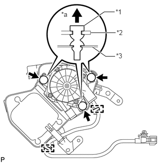
a.
A219187E02
2.417,0.25 2.198,0.25 2.198,0.25 1.771,0.542 true 1.917,0.688 2.438,0.688 true 2.427,1.188 2.229,1.188 2.229,1.188 1.948,0.99 true 1.292,0.219 1.469,0.406 0.177,0.188 10 false *a 2.438,0.167 2.625,0.344 0.188,0.177 10 false *1 2.458,0.604 2.646,0.781 0.188,0.177 10 false *2 2.448,1.094 2.635,1.271 0.188,0.177 10 false *3

Install the 3 insulators to the air pump.

Text in Illustration
*1 Insulator
*2 Air Pump
*3 Air Pump Bracket
*a Top


b.

Attach the 2 wire harness clamps to the air pump bracket.


Hide 17341 2.INSTALL NO. 1 AIR INJECTION SYSTEM HOSE
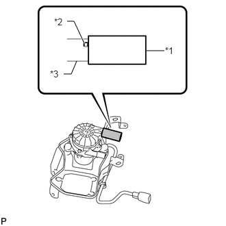
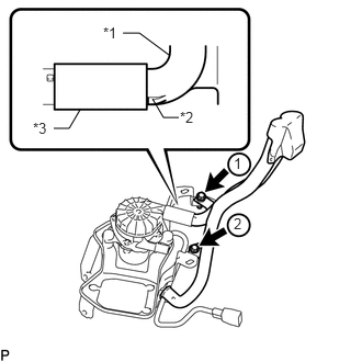
a.
A218492E02
2.229,0.771 2.5,0.771 false 1.021,0.323 1.125,0.323 1.125,0.323 1.281,0.656 true 0.969,1.125 1.083,1.125 1.083,1.125 1.167,0.927 false 2.51,0.688 2.688,0.854 0.177,0.167 10 false *1 0.823,0.25 1,0.417 0.177,0.167 10 false *2 0.76,1.042 0.938,1.208 0.177,0.167 10 false *3

Install the No. 1 air injection system hose to the air pump assembly.

Text in Illustration
*1 No. 1 Air Injection System Hose
*2 Protrusion
*3 Air Pump Assembly

HINT:

Push the No. 1 air injection system hose onto the air pump assembly until it contacts the protrusion as shown in the illustration.


Hide 17621A 3.INSTALL AIR PUMP INLET

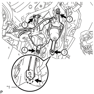
a.
U163660E02
0.51,1.219 0.656,1.219 0.656,1.219 0.76,1.042 false 1.698,1.115 1.552,1.115 1.552,1.115 1.448,0.938 false 1.167,0.313 1.323,0.313 1.323,0.313 1.604,0.521 false 0.979,0.229 1.146,0.406 0.167,0.177 10 false *1 1.708,1.031 1.875,1.208 0.167,0.177 10 false *2 0.313,1.135 0.479,1.313 0.167,0.177 10 false *3 2.219,1.469 2.323,1.635 0.104,0.167 10 false 1 2.219,2.042 2.344,2.208 0.125,0.167 10 false 2

Install the air pump inlet to the No. 1 air injection system hose.

Text in Illustration
*1 Air Pump Inlet
*2 Stopper
*3 No. 1 Air Injection System Hose

HINT:

Insert the air pump inlet until its stopper contacts the No. 1 air injection system hose as shown in the illustration.


b.

Install the 2 bolts and tighten them in the order shown in the illustration.

Torque:
8.0 N*m (82 kgf*cm, 71 in.*lbf)


Hide 17610C 4.INSTALL AIR PUMP ASSEMBLY

a.
U163494E02
0.417,3.188 0.583,3.188 0.583,3.188 0.979,2.979 true 2.51,0.604 2.646,0.781 0.135,0.177 10 false 2 2.323,1.823 2.458,2 0.135,0.177 10 false 3 0.854,1.729 0.99,1.906 0.135,0.177 10 false 4 0.24,3.104 0.396,3.271 0.156,0.167 10 false *1 0.865,0.813 1,0.99 0.135,0.177 10 false 1

Attach the claw of the air pump bracket to the elongated hole in the body to position the air pump bracket.

Text in Illustration
*1 Claw


b.

Install the 2 bolts and 2 nuts and tighten them in the order shown in the illustration.

Torque:
18 N*m (184 kgf*cm, 13 ft.*lbf)


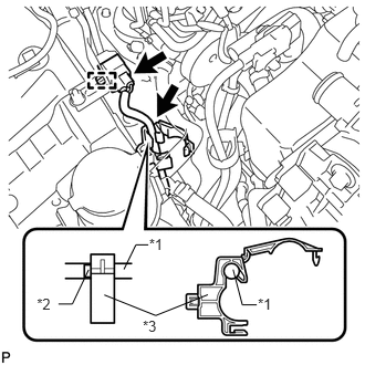
c.
A266123E01
1.404,2.215 1.585,2.379 0.181,0.164 10 *1 0.347,2.779 0.528,2.943 0.181,0.164 10 *2 0.55,2.863 0.681,2.863 0.681,2.863 0.835,2.539 false 1.344,2.985 1.526,3.149 0.181,0.164 10 *3 2.428,2.78 2.610,2.944 0.181,0.164 10 *1 1.397,2.306 1.279,2.306 1.279,2.306 1.167,2.536 false 2.417,2.871 2.282,2.871 2.282,2.871 2.195,2.538 false 0.982,2.777 1.466,2.971 1.466,2.971 1.957,2.775 false

Connect the wire harness to the clamp at the location shown in the illustration.

Text in Illustration
*1 Wire Harness
*2 Paint Mark
*3 Clamp


d.

Attach the connector clamp to the bracket.


e.

Connect the connector.


Hide 17343 5.INSTALL NO. 3 AIR INJECTION SYSTEM HOSE
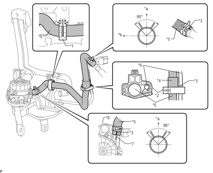
A273608E01
2.343,1.468 2.511,1.640 0.168,0.172 10 *1 1.297,1.155 1.465,1.327 0.168,0.172 10 *5 1.455,1.218 1.546,1.218 1.546,1.218 1.682,1.015 false 4.853,0.21 5.021,0.382 0.168,0.172 10 *a 4.595,0.475 4.936,0.663 0.341,0.188 10 90° 3.972,1.083 4.143,1.250 0.171,0.167 10 *b 6.674,0.616 6.841,0.789 0.168,0.172 10 *3 5.596,1.241 5.764,1.413 0.168,0.172 10 *5 5.757,1.309 5.847,1.309 5.847,1.309 5.937,0.956 false 6.665,0.682 6.562,0.682 6.562,0.682 6.376,0.913 false 5.131,3.461 5.298,3.634 0.168,0.172 10 *5 4.534,2.997 5.231,3.452 5.231,3.452 5.817,3.224 false 4.648,2.119 4.816,2.292 0.168,0.172 10 *6 4.949,2.899 4.828,2.2 4.828,2.2 6.082,2.466 false 5.28,2.635 5.448,2.807 0.168,0.172 10 *4 5.439,2.706 5.789,2.706 false 6.52,2.645 6.688,2.817 0.168,0.172 10 *3 6.511,2.718 6.359,2.718 6.359,2.718 6.108,2.868 false 5.218,3.138 5.386,3.310 0.168,0.172 10 *2 5.118,2.946 5.314,3.125 5.314,3.125 5.495,3.011 false 3.558,3.889 3.726,4.061 0.168,0.172 10 *8 3.551,3.961 3.486,3.961 3.486,3.961 3.444,4.152 false 4.438,4.025 4.606,4.197 0.168,0.172 10 *5 4.013,4.094 4.423,4.094 false 4.357,4.398 4.525,4.570 0.168,0.172 10 *3 3.933,4.466 4.343,4.466 false 4.374,4.776 4.541,4.948 0.168,0.172 10 *7 4.363,4.845 4.216,4.845 4.216,4.845 3.929,4.604 false 5.242,3.913 5.410,4.085 0.168,0.172 10 *a 5.485,4.144 5.826,4.332 0.341,0.188 10 90° 2.338,1.54 2.212,1.54 2.212,1.54 2.107,1.314 false

Text in Illustration
*1 Clamp A *2 Clamp B
*3 Paint Mark *4 Protector
*5 No. 3 Air Injection System Hose *6 Wire Harness
*7 Protrusion *8 Air Pump Assembly
*a Top *b Front

a.

Inside front fender RH:

i.

Connect the No. 3 air injection system hose to the air pump assembly at the location shown in the illustration.

HINT:

Align the paint mark of the No. 3 air injection system hose with the protrusion of the air pump assembly.


ii.

Attach clamp A to the air pump bracket.


b.

Inside engine room:

i.

Connect the No. 3 air injection system hose to the air tube at the location shown in the illustration.


ii.

Align the bottom edge of the protector of the No. 3 air injection system hose with clamp B and attach the clamp.


Hide 53875A 6.CONNECT FRONT FENDER LINER RH

a.

Install the fender liner with the 4 clips.


b.

Using a T30 "TORX" socket, install the 2 screws.


c.

Connect the liner to the front bumper cover with the screw.


Hide 53782 7.INSTALL FRONT FENDER APRON TRIM PACKING A

Hide 53805 8.INSTALL FRONT FENDER SPLASH SHIELD SUB-ASSEMBLY RH