1GR-FE INTAKE / EXHAUST EXHAUST MANIFOLD INSTALLATION
PROCEDURE

 89467B
1.INSTALL AIR FUEL RATIO SENSOR (for Bank 2 Sensor 1)
17105
2.INSTALL EXHAUST MANIFOLD SUB-ASSEMBLY LH
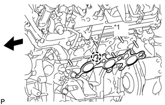
Install a new gasket to the cylinder head.
| *1 | Protrusion |

|
Front |
- NOTICE:
-
Be careful of the installation direction.
Temporarily install the manifold with 6 new nuts.
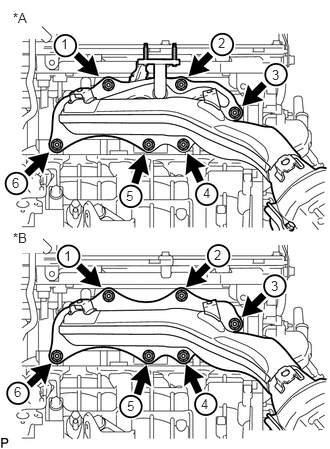
Tighten the 6 nuts in the sequence shown in the illustration.
- Torque:
- 21 N*m (214 kgf*cm, 15 ft.*lbf)
| *A | w/ Secondary Air Injection System |
| *B | w/o Secondary Air Injection System |
Connect the air fuel ratio sensor connector.
17168
3.INSTALL NO. 2 EXHAUST MANIFOLD HEAT INSULATOR
Install the heat insulator with the 3 bolts.
- Torque:
- 13 N*m (133 kgf*cm, 10 ft.*lbf)
17362
4.INSTALL NO. 2 AIR TUBE (w/ Secondary Air Injection System)
17119
5.INSTALL NO. 2 MANIFOLD STAY
Install the No. 2 manifold stay with the 3 bolts.
- Torque:
- 40 N*m (408 kgf*cm, 30 ft.*lbf)
89467B
6.INSTALL AIR FUEL RATIO SENSOR (for Bank 1 Sensor 1)
17104
7.INSTALL EXHAUST MANIFOLD SUB-ASSEMBLY RH
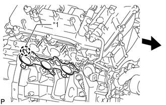
Install a new gasket to the cylinder head.
| *1 | Protrusion |
|
|
Front |
- NOTICE:
-
Be careful of the installation direction.
Temporarily install the manifold with 6 new nuts.
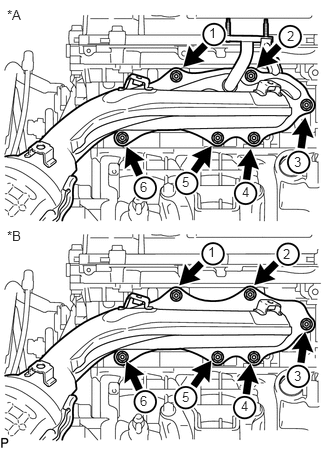
Tighten the 6 nuts in the sequence shown in the illustration.
- Torque:
- 21 N*m (214 kgf*cm, 15 ft.*lbf)
| *A | w/ Secondary Air Injection System |
| *B | w/o Secondary Air Injection System |
Connect the air fuel ratio sensor connector.
17167
8.INSTALL NO. 1 EXHAUST MANIFOLD HEAT INSULATOR
Install the heat insulator with the 3 bolts.
- Torque:
- 13 N*m (133 kgf*cm, 10 ft.*lbf)
45203A
9.CONNECT NO. 2 STEERING INTERMEDIATE SHAFT SUB-ASSEMBLY
for Manual Tilt and Manual Telescopic Steering Column: (See page Steering>STEERING COLUMN>STEERING COLUMN ASSEMBLY (for Manual Tilt and Manual Telescopic Steering Column)>INSTALLATION)
for Power Tilt and Power Telescopic Steering Column: (See page Steering>STEERING COLUMN>STEERING COLUMN ASSEMBLY (for Power Tilt and Power Telescopic Steering Column)>INSTALLATION)
17361
10.INSTALL AIR TUBE (w/ Secondary Air Injection System)
17118
11.INSTALL MANIFOLD STAY
Install the manifold stay with the 3 bolts.
- Torque:
- 40 N*m (408 kgf*cm, 30 ft.*lbf)
17410
12.INSTALL FRONT EXHAUST PIPE ASSEMBLY
51442
13.INSTALL NO. 2 ENGINE UNDER COVER
51405A
14.INSTALL NO. 1 ENGINE UNDER COVER SUB-ASSEMBLY
53805
15.INSTALL FRONT FENDER SPLASH SHIELD SUB-ASSEMBLY RH
53806
16.INSTALL FRONT FENDER SPLASH SHIELD SUB-ASSEMBLY LH
17.INSTALL AIR CLEANER CASE SUB-ASSEMBLY
18.INSTALL AIR CLEANER CAP AND HOSE
11259
19.INSTALL V-BANK COVER
20.INSPECT FOR EXHAUST GAS LEAK
If gas is leaking, tighten the areas necessary to stop the leak. Replace damaged parts as necessary.
53783
21.INSTALL FRONT FENDER APRON TRIM PACKING B
w/ KDSS:
Install the front fender apron trim packing B with the 3 clips.
w/o KDSS:
Install the front fender apron trim packing B with the 4 clips.
53782
22.INSTALL FRONT FENDER APRON TRIM PACKING A
Install the front fender apron trim packing A with the 3 clips.
53785B
23.INSTALL FRONT FENDER APRON TRIM PACKING D
Install the front fender apron trim packing D with the 4 clips.
53784
24.INSTALL FRONT FENDER APRON TRIM PACKING C
Install the front fender apron trim packing C with the 4 clips.