RM2660E
_51
Engine / Hybrid System
_052785
1UR-FE EMISSION CONTROL
_0255138
AIR SWITCHING VALVE(for Bank 2)
A
1UR-FE EMISSION CONTROL AIR SWITCHING VALVE(for Bank 2) INSTALLATION
PROCEDURE

 25710
1.INSTALL AIR SWITCHING VALVE ASSEMBLY
a.
0.198,1.406 0.198,1.281
0.198,1.281 0.396,0.969
true
1.271,0.76 1.635,0.76
true
1.333,0.188 0.604,0.188
0.604,0.188 0.729,0.563
true
1.646,0.656 1.813,0.823
0.167,0.167
10
false
*1
1.365,0.104 1.531,0.271
0.167,0.167
10
false
*2
0.115,1.438 0.281,1.604
0.167,0.167
10
false
*3
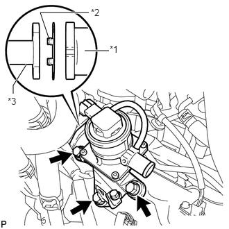
Install a new gasket and the air switching valve with the 3 bolts.
- Torque:
- 24 N*m (245 kgf*cm, 18 ft.*lbf)
| *1 | Air Switching Valve |
| *2 | Claw |
| *3 | No. 3 Air Tube |
- NOTICE:
-
Make sure the claws of the gasket are not caught between the air switching valve and No. 3 air tube.
b.
Install the 2 bolts.
- Torque:
- 10 N*m (102 kgf*cm, 7 ft.*lbf)
c.
Attach the wire harness clamp and connect the air switching valve connector.
17341
2.CONNECT NO. 1 AIR INJECTION SYSTEM HOSE
a.
1.552,2.573 1.615,2.573
1.615,2.573 1.844,2.396
true
2.385,2.479 2.323,2.479
2.323,2.479 2.167,2.552
true
1.344,2.5 1.552,2.677
0.208,0.177
10
true
*1
2.448,2.385 2.667,2.615
0.219,0.229
10
true
*2
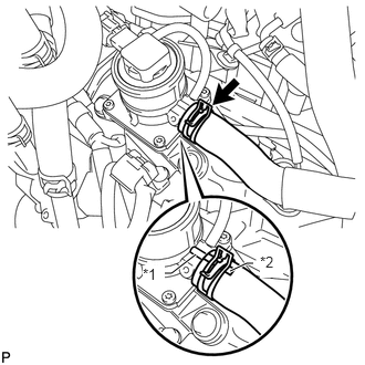
Align the paint mark with the projection and connect the No. 1 air injection system hose.
| *1 | Protrusion |
| *2 | Paint Mark |
- HINT:
-
Make sure the direction of the hose clamp is as shown in the illustration.
12263
3.CONNECT NO. 3 PCV HOSE
a.
Connect the No. 3 PCV hose.
4.INSTALL AIR CLEANER CAP AND HOSE
11209
5.INSTALL V-BANK COVER SUB-ASSEMBLY