1VD-FTV INTAKE / EXHAUST INTERCOOLER INSTALLATION
PROCEDURE

 12631C
1.INSTALL ENGINE COVER BRACKET
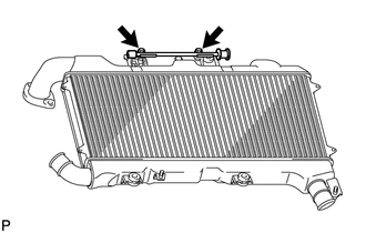
Install the engine cover bracket with the 2 bolts.
- Torque:
- 9.0 N*m (92 kgf*cm, 80 in.*lbf)
17940D
2.INSTALL INTERCOOLER ASSEMBLY
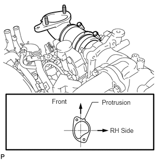
Install a new gasket to the air tube RH.
- HINT:
-
Install the gasket with the protrusion facing as shown in the illustration.
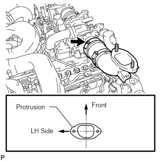
Install a new gasket to the air tube LH.
- HINT:
-
Install the gasket with the protrusion facing as shown in the illustration.
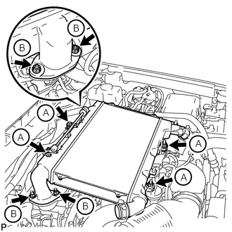
Align the No. 1 and No. 2 air hoses and intercooler pipes and connect them, and install the intercooler with the 2 bolts and 2 nuts labeled A in the illustration.
- Torque:
- 21 N*m (214 kgf*cm, 15 ft.*lbf)
Temporarily install the 4 nuts labeled B in the illustration.
Tighten the air tube LH and RH with the 4 nuts labeled B shown in the illustration.
- Torque:
- 21 N*m (214 kgf*cm, 15 ft.*lbf)
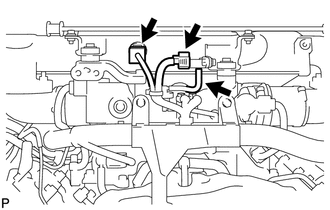
Connect the vacuum hose, intake air temperature sensor connector and turbo pressure sensor connector.
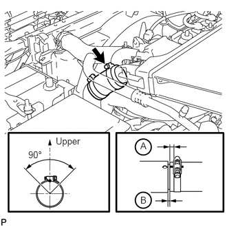
Tighten the clamp of the No. 2 air hose.
- Torque:
- 6.3 N*m (64 kgf*cm, 56 in.*lbf)
- HINT:
- ·
Align the paint mark of the air hose with the protrusion and push in the air hose so that distance B is 0 to 3 mm (0 to 0.118 in.).
·Position the clamp so that distance A is 2 to 6 mm (0.0787 to 0.236 in.).
·Make sure the direction of the hose clamp is as shown in the illustration.
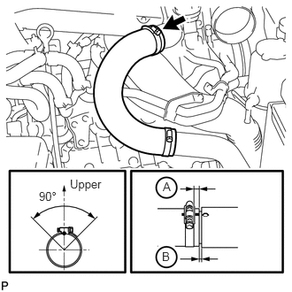
Tighten the clamp of the No. 1 air hose.
- Torque:
- 6.3 N*m (64 kgf*cm, 56 in.*lbf)
- HINT:
- ·
Align the paint mark of the air hose with the protrusion and push in the air hose so that distance B is 0 to 3 mm (0 to 0.118 in.).
·Position the clamp so that distance A is 2 to 6 mm (0.0787 to 0.236 in.).
·Make sure the direction of the hose clamp is as shown in the illustration.
12601E
3.INSTALL NO. 1 ENGINE COVER SUB-ASSEMBLY
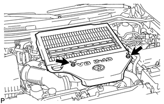
Install the engine cover with the 2 nuts.
- Torque:
- 8.0 N*m (82 kgf*cm, 71 in.*lbf)
55781E
4.INSTALL COWL TOP VENTILATOR LOUVER SUB-ASSEMBLY
53383
5.INSTALL HOOD TO COWL TOP SEAL
53883F
6.INSTALL FRONT FENDER MAIN SEAL LH
53882H
7.INSTALL FRONT FENDER MAIN SEAL RH
85221B
8.INSTALL FRONT WIPER ARM LH
85211B
9.INSTALL FRONT WIPER ARM RH
53292A
10.INSTALL UPPER RADIATOR SUPPORT SEAL