AB60F AUTOMATIC TRANSMISSION / TRANSAXLE TRANSMISSION WIRE INSTALLATION
PROCEDURE

 82125J
1.INSTALL TRANSMISSION WIRE
Coat the 2 new O-rings with automatic transmission fluid.
Install the 2 O-rings to the No. 1 transmission wire and No. 2 transmission wire.
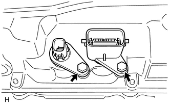
Install the No. 1 transmission wire and No. 2 transmission wire with the 2 bolts.
- Torque:
- 5.4 N*m (55 kgf*cm, 48 in.*lbf)
- NOTICE:
- ·
When reusing the transmission wire, inspect the O-ring.
·Make sure that the O-ring is not cracked or jammed when installing the transmission wire.
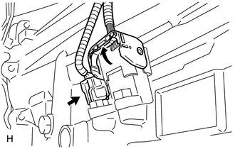
Connect the No. 2 transmission wire connector and No. 1 transmission wire connector.
- HINT:
-
Push up the lever until the claw of the transmission wire connector makes a connection sound.
82125J
2.CONNECT TRANSMISSION WIRE
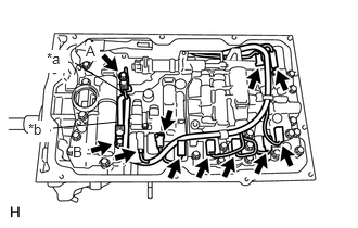
Connect the 9 connectors to the solenoid valves.
| *a | Orange |
| *b | Blue |
Coat the 2 new O-rings with ATF and install them to the 2 ATF temperature sensors.
Connect the 2 ATF temperature sensors with the 2 clamps and 2 bolts.
- Torque:
- for bolt A : 10 N*m (102 kgf*cm, 7 ft.*lbf)
- for bolt B : 11 N*m (112 kgf*cm, 8 ft.*lbf)
- HINT:
-
Each bolt length is indicated below.
-
12 mm (0.472 in.) for bolt A
36 mm (1.41 in.) for bolt B
35330
3.INSTALL VALVE BODY OIL STRAINER ASSEMBLY
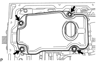
Coat a new O-ring with ATF and install it to the valve body oil strainer assembly.
- NOTICE:
-
Ensure that the O-ring is not twisted or pinched.
Install the valve body oil strainer assembly to the transmission valve body assembly with the 4 bolts.
- Torque:
- 10 N*m (102 kgf*cm, 7 ft.*lbf)
35106
4.INSTALL AUTOMATIC TRANSMISSION OIL PAN SUB-ASSEMBLY
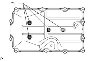
Install the 4 transmission oil cleaner magnets to the automatic transmission oil pan sub-assembly as shown in the illustration.
| *1 | Transmission Oil Cleaner Magnet |
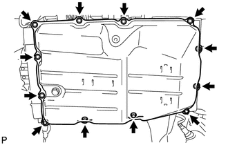
Install a new automatic transmission oil pan gasket and the automatic transmission oil pan subassembly with the 12 bolts.
- Torque:
- 7.4 N*m (75 kgf*cm, 65 in.*lbf)
- NOTICE:
-
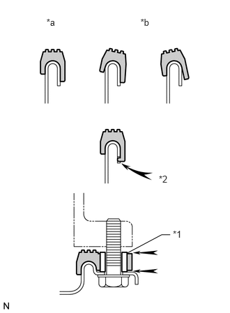 0.694,0.247 0.897,0.413 0.203,0.165 10 *a 2.099,0.247 2.310,0.403 0.211,0.156 10 *b 2.374,2.599 2.599,2.757 0.225,0.158 10 *2 2.584,3.417 2.796,3.607 0.213,0.191 10 *1 1.899,3.782 2.416,3.507 2.416,3.507 2.544,3.507 false
- ·
Make sure that automatic transmission oil pan gasket seal surface and automatic transmission oil pan sub-assembly contact surface are free of oil and foreign matter.
·Install the automatic transmission oil pan gasket so that there is no slack in the automatic transmission oil pan gasket, and the entire seal surface is level.
·Make sure that the 12 protrusions are properly engaged to the automatic transmission oil pan sub-assembly.
·When installing the automatic transmission oil pan sub-assembly, make sure that the automatic transmission oil pan gasket is not pinched between a sleeve and the seal surface of the automatic transmission case sub-assembly.
| *1 | Sleeve |
| *2 | Protrusion |
| *a | Correct |
| *b | Incorrect |
5.ADD AUTOMATIC TRANSMISSION FLUID
51440
6.INSTALL OIL PAN PROTECTOR ASSEMBLY
51442
7.INSTALL NO. 2 ENGINE UNDER COVER