RM2660E
_52
Drivetrain
_052806
A750F AUTOMATIC TRANSMISSION / TRANSAXLE
_0255289
SHIFT LEVER
A
A750F AUTOMATIC TRANSMISSION / TRANSAXLE SHIFT LEVER INSTALLATION
PROCEDURE

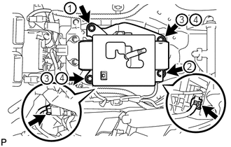
 1.INSTALL TRANSMISSION FLOOR SHIFT ASSEMBLY
2.667,0.208 2.781,0.365
0.115,0.156
10
false
3
0.656,1.083 0.771,1.24
0.115,0.156
10
false
3
0.885,1.073 1,1.229
0.115,0.156
10
false
4
2.875,0.208 2.99,0.365
0.115,0.156
10
false
4
2.781,0.906 2.896,1.063
0.115,0.156
10
false
2
1,0.042 1.115,0.198
0.115,0.156
10
false
1
a.
Install the floor shift with the 4 bolts. Tighten the bolts in the order shown in the illustration.
- Torque:
- 14 N*m (143 kgf*cm, 10 ft.*lbf)
b.
Connect the 2 connectors.
33702B
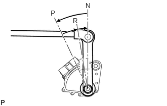
2.CONNECT FLOOR SHIFT GEAR SHIFTING ROD SUB-ASSEMBLY
1.042,0.188 1.177,0.365
0.135,0.177
10
false
P
1.5,0.344 1.635,0.521
0.135,0.177
10
false
R
1.76,0.031 1.896,0.208
0.135,0.177
10
false
N
a.
Turn the control shaft lever RH of the park/neutral position switch counterclockwise until it stops, and then turn it clockwise 2 notches to set it to the N position.
b.
Move the shift lever to N.
c.
0.883,0.134 1.301,0.311
0.418,0.177
10
Lever
1.954,0.439 1.501,0.237
1.501,0.237 1.365,0.237
false
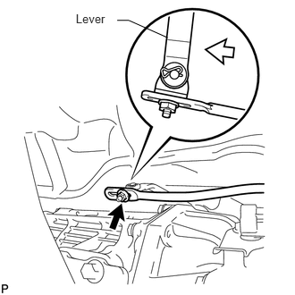
Temporarily install the floor shift gear shifting rod with the nut.
d.
Tighten the nut while lightly pushing the lever rearward.
- Torque:
- 13 N*m (130 kgf*cm, 9 ft.*lbf)
3.INSTALL FRONT CONSOLE BOX (w/o Cool Box)
4.INSTALL FRONT CONSOLE BOX (w/ Cool Box)