SUSPENSION CONTROL SUSPENSION CONTROL SYSTEM(w/ KDSS) ON-VEHICLE INSPECTION
PROCEDURE

 1.MEASURE VEHICLE HEIGHT
- NOTICE:
- ·
Perform the inspection on a level surface.
·Ensure that the wheels are on the ground and facing straight ahead.
·Perform the inspection with the vehicle load completely on the suspension.
- HINT:
- ·
Perform this step with the fuel tank full.
·If there are any parts installed to the vehicle which place any unbalanced load on the left or right side of the vehicle, remove them.
Set the tire pressure to the specified value(s) (See page Suspension>TIRE / WHEEL>TIRE AND WHEEL SYSTEM>INSPECTION).
Bounce the vehicle to stabilize the suspension.
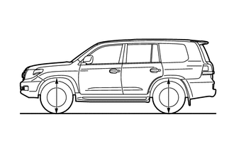
Measure the height from the ground at the part of the fender directly above the center of the wheel and check the difference between the left and right sides.
- Height difference of left and right sides:
15 mm (0.591 in.) or less
- HINT:
- ·
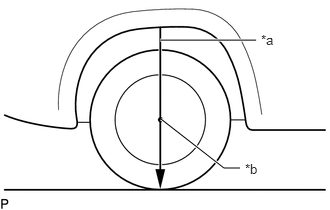 1.677,1.24 2.333,1.75 2.333,1.75 2.5,1.75 true 1.667,0.417 2.667,0.417 true 2.552,1.677 2.76,1.875 0.208,0.198 10 true *b 2.719,0.333 2.927,0.531 0.208,0.198 10 true *a
*a String *b Wheel center
Hang a string from the fender to determine the position where it passes through the center of the wheel (center of the center ornament) and measure the height as shown in the illustration.
·When the difference in vehicle height between the left and right sides is outside of the specification, perform air bleeding.
Click hereSuspension>SUSPENSION CONTROL>SUSPENSION CONTROL SYSTEM (w/ KDSS)>BLEEDING
2.VEHICLE TILT CALIBRATION
- NOTICE:
- ·
Perform the inspection on a level surface.
·Ensure that the wheels are on the ground and facing straight ahead.
·Perform the inspection with the vehicle load completely on the suspension.
- HINT:
- ·
Perform this step with the fuel tank full.
·If there are any parts installed to the vehicle which place any unbalanced load on the left or right side of the vehicle, remove them.
Remove the stabilizer control valve protector (See page Suspension>SUSPENSION CONTROL>STABILIZER CONTROL VALVE(w/ KDSS)>REMOVAL).
Using a 5 mm socket hexagon wrench or an 8 mm socket wrench, loosen the lower and upper chamber shutter valves of the stabilizer control with accumulator housing 2.0 to 3.5 turns.
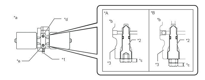
| *A | for Type A | *B | for Type B |
| *1 | Bleeder Plug | *2 | Shutter Valve |
| *3 | Block | - | - |
| *a | Bottom view of stabilizer control with accumulator housing | *b | Side view of stabilizer control with accumulator housing |
| *c | 2.0 to 3.5 mm | *d | Upper Chamber Shutter Valve |
| *e | Lower Chamber Shutter Valve | - | - |
- NOTICE:
- ·
When loosening a shutter valve, make sure that the end protrudes 2 to 3.5 mm (0.0787 to 0.137 in.) from the surface of the block, and do not turn the shutter valve any further.
·Do not remove the shutter valves.
- HINT:
-
By loosening the shutter valves, the upper and lower chamber will be fully connected, and the vehicle height is corrected by the equalization of the upper and lower chamber oil pressure.
Bounce the vehicle to stabilize the suspension.
Check the difference in height between the left and right sides of the vehicle. Refer to Measure Vehicle Height.
- HINT:
-
When the vehicle height of the left and right side of the vehicle is not within the specified range, bleed the air (See page Suspension>SUSPENSION CONTROL>SUSPENSION CONTROL SYSTEM (w/ KDSS)>BLEEDING).
Using a 5 mm socket hexagon wrench or an 8 mm socket wrench, tighten the lower and upper chamber shutter valves of the stabilizer control with accumulator housing.
- Torque:
- 14 N*m (140 kgf*cm, 10 ft.*lbf)
Install the stabilizer control valve protector (See page Suspension>SUSPENSION CONTROL>STABILIZER CONTROL VALVE(w/ KDSS)>INSTALLATION).
3.INSPECT FOR SUSPENSION FLUID LEAK
- CAUTION:
-
Fluid is pumped into the system at a high pressure of approximately 3 MPa (30.6 kgf/cm2, 435 psi). If a fluid leak is discovered, immediately release the pressure and repair the fluid leak.
Perform a driving test.
Check for fluid leakage from the parts and connections.
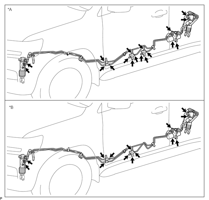
| *A | for Stabilizer Control Adapter 2 Type | *B | for Stabilizer Control Adapter 1 Type |