Home › Brake › BRAKE CONTROL / DYNAMIC CONTROL SYSTEMS › VEHICLE STABILITY CONTROL SYSTEM › 2014.08–2015.08
RM2660E _54 Brake _052819 BRAKE CONTROL / DYNAMIC CONTROL SYSTEMS _0255415 VEHICLE STABILITY CONTROL SYSTEM J

BRAKE CONTROL / DYNAMIC CONTROL SYSTEMS  VEHICLE STABILITY CONTROL SYSTEM  Crawl Indicator Light Remains ON  


DESCRIPTION

When CRAWL starts after operating the CRAWL switch, the CRAWL indicator light turns on. While CRAWL is in the process of stopping, the CRAWL indicator light begins blinking. When CRAWL totally stops, the CRAWL indicator light turns off.

WIRING DIAGRAM
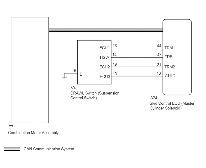
C256732E10
5.229,3.313 5.656,3.573 0.427,0.26 10 false A24 5.208,3.5 7.083,4.104 1.875,0.604 10 false Skid Control ECU (Master Cylinder Solenoid) 2.469,2.969 2.823,3.208 0.354,0.24 10 false V4 2.448,3.146 4.302,3.521 1.854,0.375 10 false CRAWL Switch (Suspension Control Switch) 5.719,1.573 6.219,1.854 0.5,0.281 10 false TRM1 5.458,1.5 5.792,1.76 0.333,0.26 10 false 44 5.719,2.24 6.26,2.5 0.542,0.26 10 false TRM2 5.74,2.542 6.313,2.813 0.573,0.271 10 false ATRC 5.729,1.885 6.344,2.135 0.615,0.25 10 false TRS 5.458,2.156 5.823,2.417 0.365,0.26 10 false 21 5.448,2.458 5.771,2.677 0.323,0.219 10 false 13 5.469,1.813 5.813,2.063 0.344,0.25 10 false 43 3.458,1.573 3.927,1.823 0.469,0.25 10 false ECU1 3.458,2.24 3.958,2.5 0.5,0.26 10 false ECU2 3.469,2.573 4.031,2.833 0.563,0.26 10 false ECU3 3.479,1.906 3.979,2.146 0.5,0.24 10 false HSW 3.917,1.5 4.208,1.729 0.292,0.229 10 false 18 3.917,2.146 4.25,2.396 0.333,0.25 10 false 19 3.917,2.479 4.25,2.719 0.333,0.24 10 false 13 3.906,1.813 4.26,2.063 0.354,0.25 10 false 14 2.5,2.365 2.896,2.604 0.396,0.24 10 false 16 2.771,2.49 3.104,2.74 0.333,0.25 10 false E 0.292,4.323 0.594,4.563 0.302,0.24 10 false E7 0.281,4.521 2.313,4.833 2.031,0.313 10 false Combination Meter Assembly 0.75,5.083 2.854,5.313 2.104,0.229 10 false : CAN Communication System

CAUTION / NOTICE / HINT

NOTICE:

After replacing the master cylinder solenoid, perform zero point calibration and store the system information (See page Brake>BRAKE CONTROL / DYNAMIC CONTROL SYSTEMS>VEHICLE STABILITY CONTROL SYSTEM>CALIBRATION).


PROCEDURE

1.CHECK CAN COMMUNICATION LINE

A

2.CHECK DTC (CAN COMMUNICATION SYSTEM)

B

GO TO CAN COMMUNICATION SYSTEM (HOW TO PROCEED WITH TROUBLESHOOTING)

C

GO TO CAN COMMUNICATION SYSTEM (HOW TO PROCEED WITH TROUBLESHOOTING)

2.CHECK DTC (CAN COMMUNICATION SYSTEM)

A

3.PERFORM ACTIVE TEST USING GTS (CRAWL CONTROL LIGHT)

B

GO TO CAN COMMUNICATION SYSTEM (HOW TO PROCEED WITH TROUBLESHOOTING)

C

GO TO CAN COMMUNICATION SYSTEM (HOW TO PROCEED WITH TROUBLESHOOTING)

3.PERFORM ACTIVE TEST USING GTS (CRAWL CONTROL LIGHT)
a.

Turn the ignition switch off.


b.

Connect the GTS to the DLC3.


c.

Turn the ignition switch to ON.


d.

Turn the GTS on.


e.

Enter the following menus: Chassis / ABS/VSC/TRC / Active Test.

ABS/VSC/TRC
Tester Display Test Part Control Range Diagnostic Note
Crawl Control Light CRAWL indicator light Indicator light ON/OFF Observe the combination meter.


f.

When performing the Crawl Control Light Active Test, check Crawl Control Light in the Data List.

ABS/VSC/TRC
Tester Display Measurement Item/Range Normal Condition Diagnostic Note
Crawl Control Light CRAWL indicator light/ ON or OFF ON: Indicator light on
OFF: Indicator light off
-

Result
Result Proceed to
Data List Display Data List Display when Performing Active Test ON/OFF Operation
ON Changes between ON and OFF A
Does not change between ON and OFF (for LHD) B
Does not change between ON and OFF (for RHD) C
OFF Changes between ON and OFF A
Does not change between ON and OFF (for LHD) B
Does not change between ON and OFF (for RHD) C


A

GO TO METER / GAUGE SYSTEM (HOW TO PROCEED WITH TROUBLESHOOTING)

B

C