VARIABLE GEAR RATIO STEERING STEERING ACTUATOR REMOVAL
CAUTION / NOTICE / HINT
- CAUTION:
-
Some of these service operations affect the SRS airbag system. Read the precautionary notices concerning the SRS airbag system before servicing the steering column (See page Vehicle Interior>SUPPLEMENTAL RESTRAINT SYSTEMS>AIRBAG SYSTEM>PRECAUTION).
- HINT:
- ·
Use the same procedure for RHD and LHD vehicles.
·The procedure listed below is for LHD vehicles.
PROCEDURE

 1.PLACE FRONT WHEELS FACING STRAIGHT AHEAD
2.DISCONNECT CABLE FROM NEGATIVE BATTERY TERMINAL
Disable the AUTO TILT AWAY function by changing the customize parameter (See page General>INTRODUCTION>REPAIR INSTRUCTION>CUSTOMIZE PARAMETERS).
- NOTICE:
-
Record the current customize parameter setting (whether the AUTO TILT AWAY function is enabled or disabled) in order to restore the current setting after finishing the operation.
- HINT:
-
Performing the above operation causes the AUTO TILT AWAY function to be disabled when the engine switch is turned off.
Turn the engine switch on (IG). Operate the tilt and telescopic switch to fully extend and lower the steering column assembly.
Turn the engine switch off and disconnect the cable from the negative (-) battery terminal.
- CAUTION:
-
Wait at least 90 seconds after disconnecting the cable from the negative (-) battery terminal to disable the SRS system.
- NOTICE:
-
When disconnecting the cable, some systems need to be initialized after the cable is reconnected (See page General>INTRODUCTION>REPAIR INSTRUCTION>INITIALIZATION).
45250
3.REMOVE STEERING COLUMN ASSEMBLY
45240J
4.REMOVE STEERING ACTUATOR ASSEMBLY
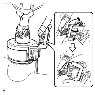
While pushing the claws on both sides of the connector, move the lock in the direction of the arrow.
Disconnect the connector.
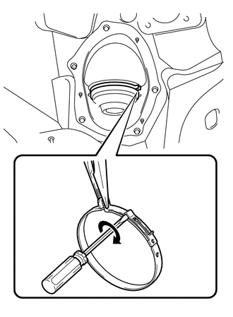
Hold the clamp with needle nose pliers, then insert a screwdriver and turn it in the direction shown in the illustration to remove the clamp of the steering column hole cover.
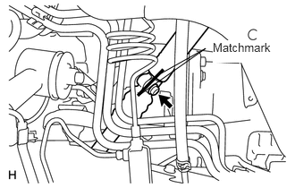
Put matchmarks on the steering actuator and No. 2 steering intermediate shaft.
Remove the bolt, and then pull out the actuator assembly toward the inside of the vehicle.