RM2660E
_56
Audio / Visual / Telematics
_052828
AUDIO / VIDEO
_0255476
REAR SEAT ENTERTAINMENT SYSTEM
J
AUDIO / VIDEO REAR SEAT ENTERTAINMENT SYSTEM Visual Mute Signal Circuit between Radio Receiver and Multi-display Controller
DESCRIPTION
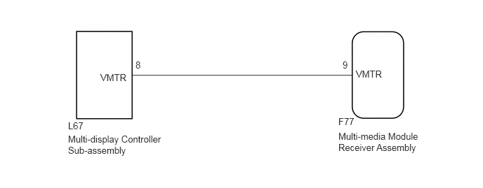
This is the visual mute signal circuit between the multi-media module receiver assembly and the multi-display controller sub-assembly.
WIRING DIAGRAM
1.49,1.073 2.031,1.219
0.542,0.146
10
false
VMTR
2.01,0.885 2.219,1.042
0.208,0.156
10
false
8
5.281,1.021 5.823,1.167
0.542,0.146
10
false
VMTR
1.01,1.99 2.458,2.375
1.448,0.385
10
false
Multi-display Controller Sub-assembly
5.021,1.948 6.406,2.344
1.385,0.396
10
false
Multi-media Module Receiver Assembly
1.01,1.792 1.385,1.979
0.375,0.188
10
false
L67
5.021,1.729 5.396,1.917
0.375,0.188
10
false
F77
5.083,0.885 5.292,1.042
0.208,0.156
10
false
9
PROCEDURE
1.CHECK MULTI-MEDIA MODULE RECEIVER ASSEMBLY
a.
0.065,0.034 0.550,0.195
0.485,0.161
10
*a
0.942,1.774 1.402,1.934
0.460,0.161
10
VMTR
2.085,1.104 1.626,1.855
1.626,1.855 1.493,1.855
false
1.565,0.35 2.028,0.510
0.463,0.161
10
F77
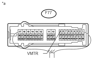
Measure the voltage according to the value(s) in the table below.
- Standard Voltage:
Tester Connection Condition Specified Condition F77-9 (VMTR) - Body ground RSE playing → Source changed Higher than 3.5 V → Below 1 V
| *a | Component with harness connected
(Multi-media Module Receiver Assembly) |
OK
PROCEED TO NEXT SUSPECTED AREA SHOWN IN PROBLEM SYMPTOMS TABLE
(See pageAudio / Visual / Telematics>AUDIO / VIDEO>REAR SEAT ENTERTAINMENT SYSTEM>PROBLEM SYMPTOMS TABLE)
NG
2.CHECK HARNESS AND CONNECTOR (MULTI-MEDIA MODULE RECEIVER ASSEMBLY - MULTI-DISPLAY CONTROLLER SUB-ASSEMBLY)
2.CHECK HARNESS AND CONNECTOR (MULTI-MEDIA MODULE RECEIVER ASSEMBLY - MULTI-DISPLAY CONTROLLER SUB-ASSEMBLY)
a.
Disconnect the F77 multi-media module receiver assembly connector.
b.
Disconnect the L67 multi-display controller sub-assembly connector.
c.
Measure the resistance according to the value(s) in the table below.
- Standard Resistance:
Tester Connection Condition Specified Condition F77-9 (VMTR) - L67-8 (VMTR) Always Below 1 Ω F77-9 (VMTR) - Body ground Always 10 kΩ or higher
OK
3.CHECK MULTI-MEDIA MODULE RECEIVER ASSEMBLY
NG
REPAIR OR REPLACE HARNESS OR CONNECTOR
3.CHECK MULTI-MEDIA MODULE RECEIVER ASSEMBLY
a.
Disconnect the multi-display controller sub-assembly connector.
b.
0.761,1.77 1.234,1.940
0.473,0.170
10
VMTR
1.275,1.339 1.081,1.738
false
0.099,0.048 0.315,0.218
0.216,0.170
10
*a
1.596,0.309 1.903,0.459
0.308,0.150
10
L67
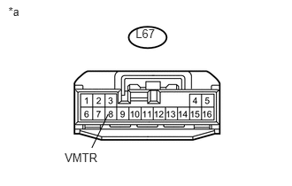
Measure the voltage according to the value(s) in the table below.
- Standard Voltage:
Tester Connection Condition Specified Condition L67-8 (VMTR) - Body ground RSE playing → Source changed Higher than 3.5 V → Below 1 V
| *a | Front view of wire harness connector
(to Multi-display Controller Sub-assembly) |
OK
REPLACE MULTI-DISPLAY CONTROLLER SUB-ASSEMBLY
NG
REPLACE MULTI-MEDIA MODULE RECEIVER ASSEMBLY