INTERIOR PANELS / TRIM INSTRUMENT PANEL SAFETY PAD REASSEMBLY
CAUTION / NOTICE / HINT
- HINT:
- ·
Use the same procedure for RHD and LHD vehicles.
·The procedure listed below is for LHD vehicles.
·A bolt without a torque specification is shown in the standard bolt chart (See page General>SPECIFICATIONS>STANDARD BOLT>SPECIFIED TORQUE FOR STANDARD BOLTS).
PROCEDURE

 55548A
1.INSTALL INSTRUMENT PANEL HOLE COVER
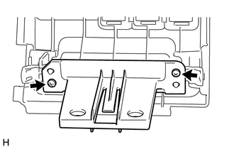
Install the instrument panel hole cover with the 2 screws.
55418B
2.INSTALL METER HOOD SPACER
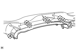
Attach the 8 claws to install the meter hood spacer.
55562B
3.INSTALL GLOVE COMPARTMENT DOOR LOCK PIN
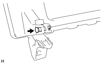
Install the glove compartment door lock pin.
55569
4.INSTALL GLOVE COMPARTMENT DOOR LOCK COVER
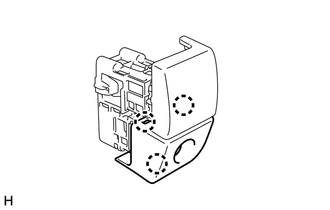
Attach the 3 claws to install the glove compartment door lock cover.
55560A
5.INSTALL GLOVE COMPARTMENT DOOR LOCK ASSEMBLY
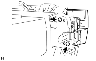
Install the glove compartment door lock assembly with the 2 screws.
58959E
6.INSTALL CONSOLE COMPARTMENT DOOR CUSHION
- HINT:
-
Use the same procedure for both console compartment door cushions.
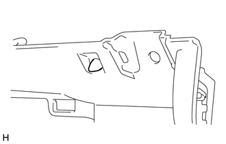
Install the console compartment door cushion.
55459D
7.INSTALL LOWER INSTRUMENT COVER LH
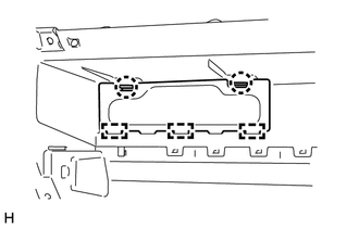
Attach the 3 guides.
Attach the 2 claws to install the lower instrument cover LH.
55512A
8.INSTALL GLOVE COMPARTMENT PLATE
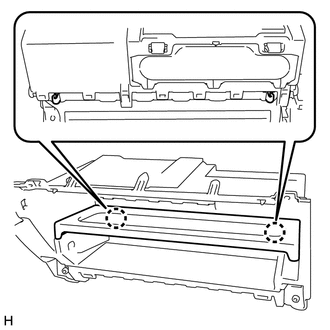
Attach the 2 claws to install the glove compartment plate.
55501A
9.INSTALL GLOVE COMPARTMENT DOOR SUB-ASSEMBLY
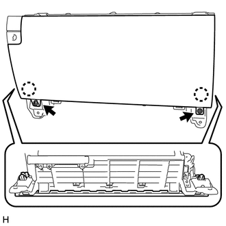
Attach the 2 claws to install the glove compartment door sub-assembly.
Install the 2 screws.
81260
10.INSTALL GLOVE BOX LIGHT ASSEMBLY
82142
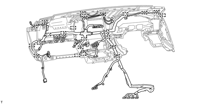
11.INSTALL NO. 2 INSTRUMENT PANEL WIRE
Attach the the clamps to install the No. 2 instrument panel wire.
86101
12.INSTALL ANTENNA CORD SUB-ASSEMBLY
w/ Navigation System:
(See page Audio / Visual / Telematics>AUDIO / VIDEO>RADIO ANTENNA CORD>INSTALLATION)
w/o Navigation System:
(See page Audio / Visual / Telematics>AUDIO / VIDEO>RADIO ANTENNA CORD>INSTALLATION)
86860
13.INSTALL NAVIGATION ANTENNA ASSEMBLY (w/ Navigation System)
55961B
14.INSTALL NO. 1 SIDE DEFROSTER NOZZLE
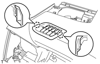
ach the 2 claws to install the No. 1 side defroster nozzle.
55962
15.INSTALL NO. 2 SIDE DEFROSTER NOZZLE
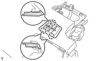
Attach the 2 claws to install the No. 2 side defroster nozzle.
55950G
16.INSTALL DEFROSTER NOZZLE ASSEMBLY
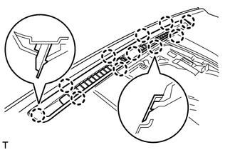
Attach the 11 claws to install the defroster nozzle assembly.
73960A
17.INSTALL INSTRUMENT PANEL PASSENGER WITHOUT DOOR AIRBAG ASSEMBLY
87212
18.INSTALL REAR NO. 1 AIR DUCT (w/ Rear Air Duct)
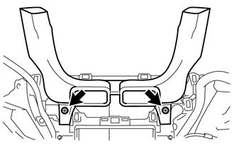
Install the rear No. 1 air duct with the 2 screws.
55835A
19.INSTALL CENTER HEATER TO REGISTER DUCT
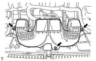
Install the center heater to register duct with the 3 screws <C>.
| *a | Screw <C> |