Home › Vehicle Exterior › DOOR / HATCH › TAIL GATE CLOSER SYSTEM › from 2015.08
RM2660E _59 Vehicle Exterior _052852 DOOR / HATCH _0255760 TAIL GATE CLOSER SYSTEM J

DOOR / HATCH  TAIL GATE CLOSER SYSTEM  Tail Gate Closer does not Operate  


WIRING DIAGRAM
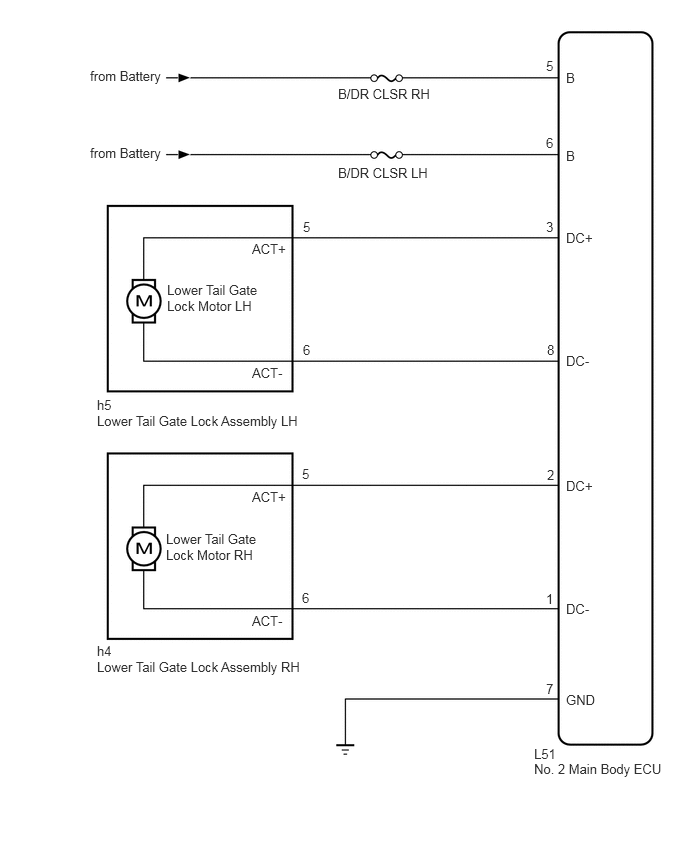
B312263E04
3.521,0.896 4.521,1.042 1,0.146 10 false B/DR CLSR RH 3.521,1.719 4.521,1.865 1,0.146 10 false B/DR CLSR LH 5.688,2.281 5.792,2.427 0.104,0.146 10 false 3 5.688,1.406 5.792,1.552 0.104,0.146 10 false 6 5.688,0.604 5.792,0.75 0.104,0.146 10 false 5 5.698,3.563 5.792,3.708 0.094,0.146 10 false 8 5.698,4.865 5.792,5.01 0.094,0.146 10 false 2 5.688,6.156 5.792,6.302 0.104,0.146 10 false 1 3.156,2.281 4.188,2.427 1.031,0.146 10 false 5 3.156,3.563 4.188,3.708 1.031,0.146 10 false 6 3.146,4.854 4.177,5 1.031,0.146 10 false 5 3.146,6.146 4.177,6.292 1.031,0.146 10 false 6 2.625,2.51 3.01,2.656 0.385,0.146 10 false ACT+ 2.625,3.802 3.01,3.948 0.385,0.146 10 false ACT- 1.74,2.938 2.771,3.271 1.031,0.333 10 false Lower Tail Gate Lock Motor LH 1.01,4.135 2.042,4.281 1.031,0.146 10 false h5 1.01,4.302 3.198,4.448 2.188,0.146 10 false Lower Tail Gate Lock Assembly LH 1.01,6.698 2.042,6.844 1.031,0.146 10 false h4 1.01,6.865 3.229,7.01 2.219,0.146 10 false Lower Tail Gate Lock Assembly RH 2.625,5.094 3.01,5.24 0.385,0.146 10 false ACT+ 2.625,6.385 3.01,6.531 0.385,0.146 10 false ACT- 1.729,5.531 2.76,5.917 1.031,0.385 10 false Lower Tail Gate Lock Motor RH 5.688,7.094 5.792,7.24 0.104,0.146 10 false 7 5.563,7.771 5.833,7.917 0.271,0.146 10 false L51 5.563,7.927 6.958,8.115 1.396,0.188 10 false No. 2 Main Body ECU 5.896,2.396 6.927,2.542 1.031,0.146 10 false DC+ 5.896,3.677 6.927,3.823 1.031,0.146 10 false DC- 5.896,4.979 6.927,5.125 1.031,0.146 10 false DC+ 5.896,6.26 6.927,6.406 1.031,0.146 10 false DC- 5.896,7.208 6.927,7.354 1.031,0.146 10 false GND 5.896,1.542 6.927,1.688 1.031,0.146 10 false B 5.896,0.729 6.927,0.875 1.031,0.146 10 false B 0.938,1.51 1.729,1.76 0.792,0.25 10 false from Battery 0.938,0.708 1.719,0.948 0.781,0.24 10 false from Battery

CAUTION / NOTICE / HINT

NOTICE:

Inspect the fuses for circuits related to this system before performing the following inspection procedure.


PROCEDURE
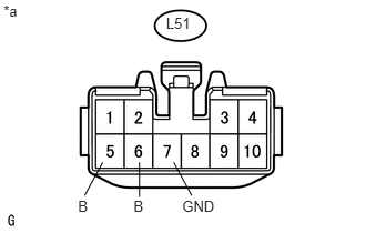
1.CHECK HARNESS AND CONNECTOR (NO. 2 MAIN BODY ECU - BATTERY AND BODY GROUND)
U163849E01
0.964,1.523 0.794,1.836 false 1.631,1.523 1.801,1.836 false 1.309,1.523 1.309,1.849 false 1.711,1.852 2.045,1.996 0.334,0.144 10 GND 1.254,1.852 1.364,1.996 0.110,0.144 10 B 0.732,1.852 0.842,1.996 0.110,0.144 10 B 0.034,0.02 0.368,0.164 0.334,0.144 10 *a 1.561,0.137 1.810,0.318 0.249,0.181 10 L51

a.

Disconnect the No. 2 main body ECU connector.


b.

Measure the voltage according to the value(s) in the table below.

Standard Voltage:
Tester Connection Condition Specified Condition
L51-5 (B) - Body ground Always 11 to 14 V
L51-6 (B) - Body ground Always 11 to 14 V


c.

Measure the resistance according to the value(s) in the table below.

Standard Resistance:
Tester Connection Condition Specified Condition
L51-7 (GND) - Body ground Always Below 1 Ω


Text in Illustration
*a Front view of wire harness connector
(to No. 2 Main Body ECU)


OK

2.INSPECT LOWER TAIL GATE LOCK ASSEMBLY

NG

REPAIR OR REPLACE HARNESS OR CONNECTOR

2.INSPECT LOWER TAIL GATE LOCK ASSEMBLY
a.

for LH:

i.

Remove the lower tail gate lock assembly LH (See page Vehicle Exterior>DOOR / HATCH>BACK DOOR>DISASSEMBLY).


ii.

Inspect the lower tail gate lock assembly LH (See page Vehicle Exterior>DOOR / HATCH>BACK DOOR>INSPECTION).


b.

for RH:

i.

Remove the lower tail gate lock assembly RH (See page Vehicle Exterior>DOOR / HATCH>BACK DOOR>DISASSEMBLY).


ii.

Inspect the lower tail gate lock assembly RH (See page Vehicle Exterior>DOOR / HATCH>BACK DOOR>INSPECTION).


Result
Result Proceed to
OK A
NG (for LH) B
NG (for RH) C


A

3.CHECK HARNESS AND CONNECTOR (LOWER TAIL GATE LOCK ASSEMBLY - NO. 2 MAIN BODY ECU)

B

REPLACE LOWER TAIL GATE LOCK ASSEMBLY LH

C

REPLACE LOWER TAIL GATE LOCK ASSEMBLY RH

3.CHECK HARNESS AND CONNECTOR (LOWER TAIL GATE LOCK ASSEMBLY - NO. 2 MAIN BODY ECU)
a.

for LH:

i.

Disconnect the h5 lower tail gate lock assembly LH connector.


ii.

Disconnect the L51 No. 2 main body ECU connector.


iii.

Measure the resistance according to the value(s) in the table below.

Standard Resistance:
Tester Connection Condition Specified Condition
h5-5 (ACT+) - L51-3 (DC+) Always Below 1 Ω
h5-6 (ACT-) - L51-8 (DC-) Always Below 1 Ω
h5-5 (ACT+) - Body ground Always 10 kΩ or higher
h5-6 (ACT-) - Body ground Always 10 kΩ or higher


b.

for RH:

i.

Disconnect the h4 lower tail gate lock assembly RH connector.


ii.

Disconnect the L51 No. 2 main body ECU connector.


iii.

Measure the resistance according to the value(s) in the table below.

Standard Resistance:
Tester Connection Condition Specified Condition
h4-5 (ACT+) - L51-2 (DC+) Always Below 1 Ω
h4-6 (ACT-) - L51-1 (DC-) Always Below 1 Ω
h4-5 (ACT+) - Body ground Always 10 kΩ or higher
h4-6 (ACT-) - Body ground Always 10 kΩ or higher


OK

NG

REPAIR OR REPLACE HARNESS OR CONNECTOR