LIGHTING (EXT) RELAY ON-VEHICLE INSPECTION
PROCEDURE

 1.INSPECT HEADLIGHT RELAY (HEAD HI, HEAD LO)
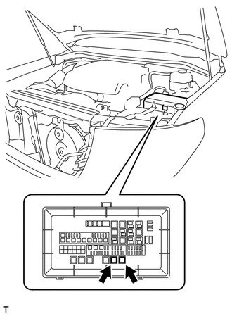
Remove the headlight relay from the engine room relay box.
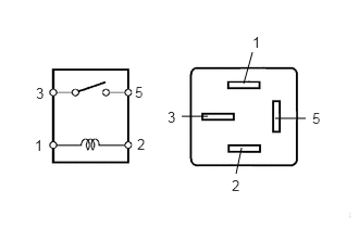
Measure the resistance according to the value(s) in the table below.
- Standard Resistance:
Tester Connection Condition Specified Condition 3 - 5 When battery voltage is not applied to terminals 1 and 2 10 kΩ or higher When battery voltage is applied to terminals 1 and 2 Below 1 Ω
If the result is not as specified, replace the relay.
Install the headlight relay to the engine room relay box.
2.INSPECT FOG LIGHT RELAY (FR FOG)
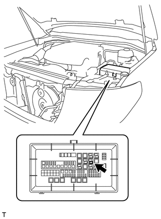
Remove the fog light relay from the engine room relay box.
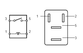
Measure the resistance according to the value(s) in the table below.
- Standard Resistance:
Tester Connection Condition Specified Condition 3 - 5 When battery voltage is not applied to terminals 1 and 2 10 kΩ or higher When battery voltage is applied to terminals 1 and 2 Below 1 Ω
If the result is not as specified, replace the relay.
Install the fog light relay to the engine room relay box.
895A0
3.INSPECT STOP LIGHT CONTROL RELAY ASSEMBLY
w/ Floor Under Cover:
Remove the No. 1 under cover (See page Vehicle Interior>INTERIOR PANELS / TRIM>INSTRUMENT PANEL SAFETY PAD>REMOVAL).
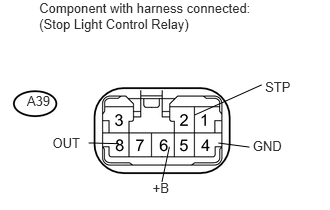
Measure the voltage according to the value(s) in the table below.
- Standard Voltage:
Tester Connection Switch Condition Specified Condition A39-6 (+B) - A39-4 (GND) Always 11 to 14 V A39-2 (STP) - Body grand Stop light switch on 11 to 14 V Stop light switch off Below 1 V A39-8 (OUT) - Body grand Stop light switch on 11 to 14 V Stop light switch off Below 1 V
If the result is not as specified, replace the stop light control relay.
w/ Floor Under Cover:
Install the No. 1 under cover (See page Vehicle Interior>INTERIOR PANELS / TRIM>INSTRUMENT PANEL SAFETY PAD>INSTALLATION).