LIGHTING (EXT) LIGHTING SYSTEM Stop Light Circuit
DESCRIPTION
When the stop light switch is turned on, current flows to the stop lights to illuminate them.
WIRING DIAGRAM
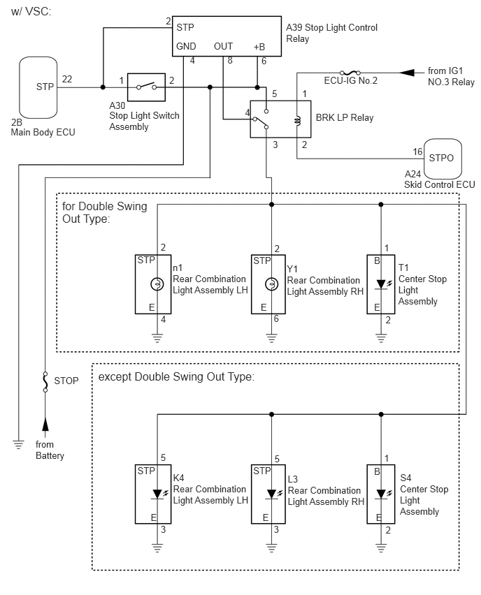
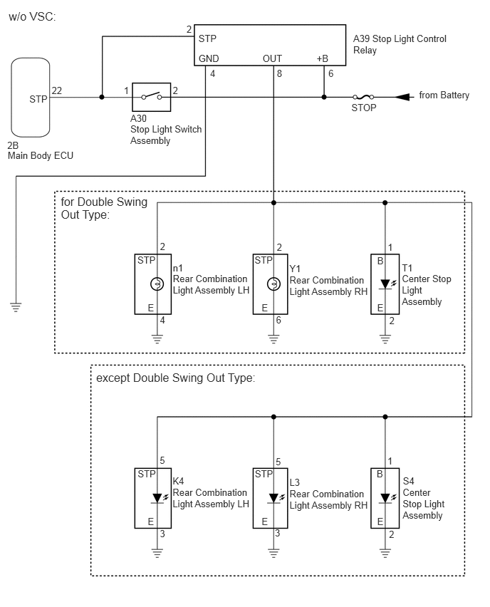
PROCEDURE
Operate the intelligent tester according to the display and select the "Data List".
| Tester Display | Measurement Item/Range | Normal Condition | Diagnostic Note |
|---|---|---|---|
| Stop Light SW | Stop light switch / ON or OFF | ON: Brake pedal depressed
OFF: Brake pedal released |
- |
- OK:
On the intelligent tester screen, each item changes between ON and OFF according to above chart
OK
NG
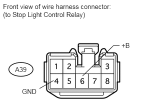
Disconnect the A39 relay connector.
Measure the voltage according to the value(s) in the table below.
- Standard Voltage:
Tester Connection Condition Specified Condition A39-6 (+B) - Body ground Always 11 to 14 V
Measure the resistance according to the value(s) in the table below.
- Standard Resistance:
Tester Connection Condition Specified Condition A39-4 (GND) - Body ground Always Below 1 Ω
OK
NG
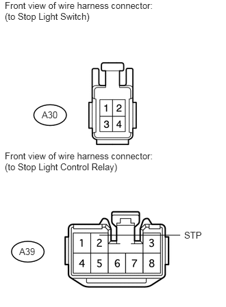
Disconnect the A30 stop light switch connector.
Disconnect the A39 relay connector.
Measure the resistance according to the value(s) in the table below.
- Standard Resistance:
Tester Connection Condition Specified Condition A30-1 - A39-2 (STP) Always Below 1 Ω A30-1 - Body ground Always 10 kΩ or higher
OK
NG
Check the vehicle type.
| Result | Proceed to |
|---|---|
| w/ VSC | A |
| w/o VSC | B |
A
B
Remove the ECU-IG No.2 fuse from the main body ECU.
Measure the resistance according to the value(s) in the table below.
- Standard Resistance:
Tester Connection Condition Specified Condition ECU-IG No.2 fuse Always Below 1 Ω
OK
NG
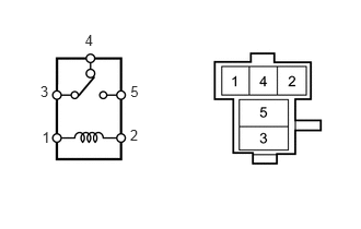
Remove the brake light relay from the engine room relay block.
Measure the resistance according to the value(s) in the table below.
- Standard Resistance:
Tester Connection Condition Specified Condition 3 - 5 Battery voltage not applied to terminals 1 and 2 10 kΩ or higher Battery voltage applied to terminals 1 and 2 Below 1 Ω 3 - 4 Battery voltage not applied to terminals 1 and 2 Below 1 Ω Battery voltage applied to terminals 1 and 2 10 kΩ or higher
OK
NG
Remove the brake light relay from the engine room relay block.
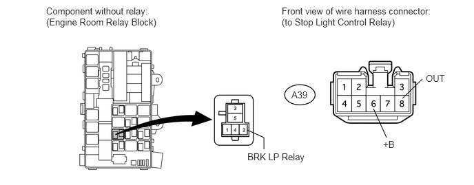
Disconnect the A39 stop light control relay connector.
Measure the resistance according to the value(s) in the table below.
- Standard Resistance:
Tester Connection Condition Specified Condition A39-8 (OUT) - Brake light relay terminal 4 Always Below 1 Ω A39-6 (+B) - Brake light relay terminal 5 A39-8 (OUT) - Body ground Always 10 kΩ or higher A39-6 (+B) - Body ground
OK
NG
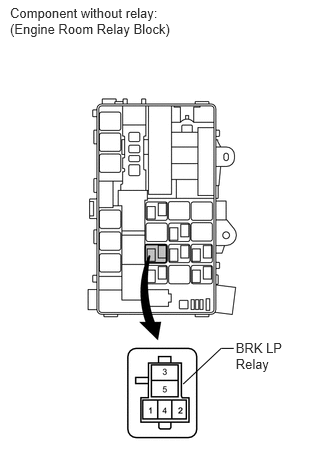
Remove the brake light relay from the engine room relay block.
Measure the voltage according to the value(s) in the table below.
- Standard Voltage:
Tester Connection Switch Condition Specified Condition Brake light relay terminal 1 - Body ground Ignition switch ON 11 to 14 V Ignition switch off Below 1 V
OK
NG
Remove the brake light relay from the engine room relay block.
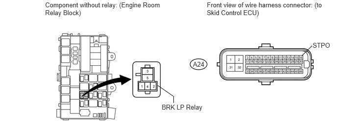
Disconnect the A24 ECU connector.
Measure the resistance according to the value(s) in the table below.
- Standard Resistance:
Tester Connection Condition Specified Condition Brake light relay terminal 2 - A24-16 (STPO) Always Below 1 Ω Brake light relay terminal 2 - Body ground Always 10 kΩ or higher
OK
NG
Check the vehicle type.
| Result | Proceed to |
|---|---|
| for Double Swing Out Type | A |
| except Double Swing Out Type | B |
A
B
Remove the brake light relay from the engine room relay block.
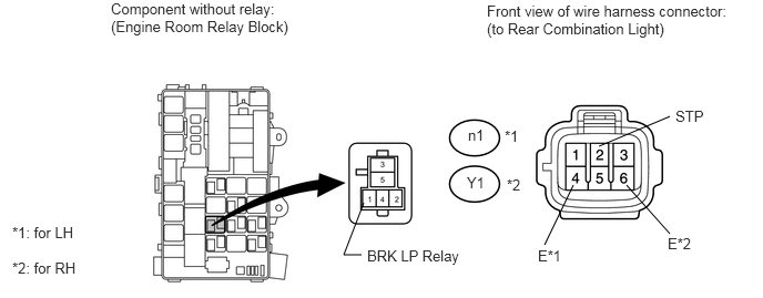
for LH:
Disconnect the n1 light connector.
Measure the resistance according to the value(s) in the table below.
- Standard Resistance:
Tester Connection Condition Specified Condition Brake light relay terminal 3 - n1-2 (STP) Always Below 1 Ω n1-4 (E) - Body ground n1-2 (STP) - Body ground Always 10 kΩ or higher
for RH:
Disconnect the Y1 light connector.
Measure the resistance according to the value(s) in the table below.
- Standard Resistance:
Tester Connection Condition Specified Condition Brake light relay terminal 3 - Y1-2 (STP) Always Below 1 Ω Y1-6 (E) - Body ground Y1-2 (STP) - Body ground Always 10 kΩ or higher
Disconnect the T1 light connector.
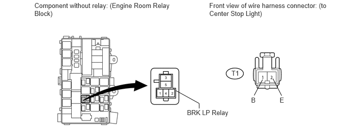
Measure the resistance according to the value(s) in the table below.
- Standard Resistance:
Tester Connection Condition Specified Condition Brake light relay terminal 3 - T1-1 (B) Always Below 1 Ω T1-2 (E) - Body ground T1-1 (B) - Body ground Always 10 kΩ or higher
OK
NG
Temporarily replace the stop light control relay with a new or normally functioning one.
Check the stop light operation.
- OK:
Stop light operation is normal.
OK
NG
Remove the brake light relay from the engine room relay block.
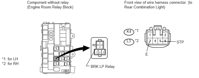
for LH:
Disconnect the K4 light connector.
Measure the resistance according to the value(s) in the table below.
- Standard Resistance:
Tester Connection Condition Specified Condition Brake light relay terminal 3 - K4-5 (STP) Always Below 1 Ω K4-3 (E) - Body ground K4-5 (STP) - Body ground Always 10 kΩ or higher
for RH:
Disconnect the L3 light connector.
Measure the resistance according to the value(s) in the table below.
- Standard Resistance:
Tester Connection Condition Specified Condition Brake light relay terminal 3 - L3-5 (STP) Always Below 1 Ω L3-3 (E) - Body ground L3-5 (STP) - Body ground Always 10 kΩ or higher
Disconnect the S4 light connector.
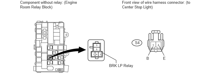
Measure the resistance according to the value(s) in the table below.
- Standard Resistance:
Tester Connection Condition Specified Condition Brake light relay terminal 3 - S4-1 (B) Always Below 1 Ω S4-2 (E) - Body ground S4-1 (B) - Body ground Always 10 kΩ or higher
OK
NG
Temporarily replace the stop light control relay with a new or normally functioning one.
Check the stop light operation.
- OK:
Stop light operation is normal.
OK
NG
Check the vehicle type.
| Result | Proceed to |
|---|---|
| for Double Swing Out Type | A |
| except Double Swing Out Type | B |
A
B
Disconnect the A39 stop light control relay connector.
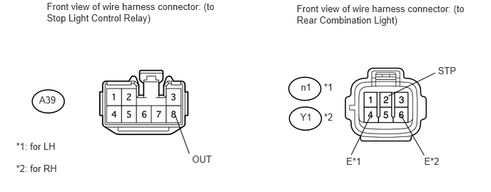
for LH:
Disconnect the n1 light connector.
Measure the resistance according to the value(s) in the table below.
- Standard Resistance:
Tester Connection Condition Specified Condition A39-8 (OUT) - n1-2 (STP) Always Below 1 Ω n1-4 (E) - Body ground n1-2 (STP) - Body ground Always 10 kΩ or higher
for RH:
Disconnect the Y1 light connector.
Measure the resistance according to the value(s) in the table below.
- Standard Resistance:
Tester Connection Condition Specified Condition A39-8 (OUT) - Y1-2 (STP) Always Below 1 Ω Y1-6 (E) - Body ground Y1-2 (STP) - Body ground Always 10 kΩ or higher
Disconnect the T1 light connector.
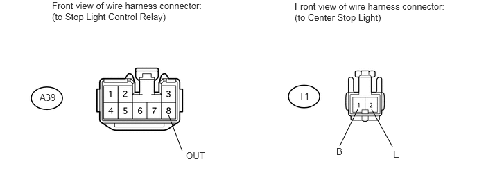
Measure the resistance according to the value(s) in the table below.
- Standard Resistance:
Tester Connection Condition Specified Condition A39-8 (OUT) - T1-1 (B) Always Below 1 Ω T1-2 (E) - Body ground T1-1 (B) - Body ground Always 10 kΩ or higher
OK
NG
Disconnect the A39 stop light control relay connector.
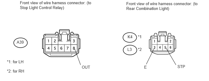
for LH:
Disconnect the K4 light connector.
Measure the resistance according to the value(s) in the table below.
- Standard Resistance:
Tester Connection Condition Specified Condition A39-8 (OUT) - K4-5 (STP) Always Below 1 Ω K4-3 (E) - Body ground K4-5 (STP) - Body ground Always 10 kΩ or higher
for RH:
Disconnect the L3 light connector.
Measure the resistance according to the value(s) in the table below.
- Standard Resistance:
Tester Connection Condition Specified Condition A39-8 (OUT) - L3-5 (STP) Always Below 1 Ω L3-3 (E) - Body ground L3-5 (STP) - Body ground Always 10 kΩ or higher
Disconnect the S4 light connector.
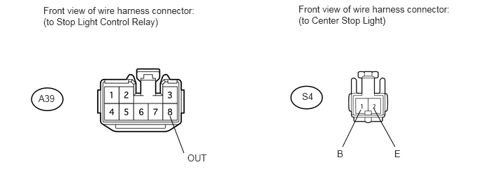
Measure the resistance according to the value(s) in the table below.
- Standard Resistance:
Tester Connection Condition Specified Condition A39-8 (OUT) - S4-1 (B) Always Below 1 Ω S4-2 (E) - Body ground S4-1 (B) - Body ground Always 10 kΩ or higher
OK
NG
Remove the STOP fuse from the engine room relay block.
Measure the resistance according to the value(s) in the table below.
- Standard Resistance:
Tester Connection Condition Specified Condition STOP fuse Always Below 1 Ω
OK
NG
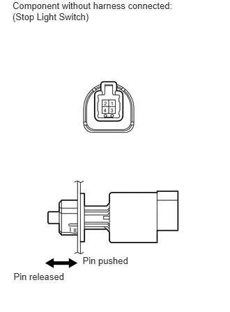
Remove the stop light switch (See page Vehicle Exterior>LIGHTING (EXT)>STOP LIGHT SWITCH>REMOVAL).
Measure the resistance according to the value(s) in the table below.
- Standard Resistance:
Tester Connection Switch Condition Specified Condition 1 - 2 Switch pin released Below 1 Ω 1 - 2 Switch pin pushed in 10 kΩ or higher
OK
NG
Disconnect the A30 stop light switch connector.
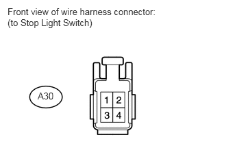
Measure the voltage according to the value(s) in the table below.
- Standard Voltage:
Tester Connection Condition Specified Condition A30-2 - Body ground Always 11 to 14 V
OK
NG
Disconnect the A30 stop light switch connector.
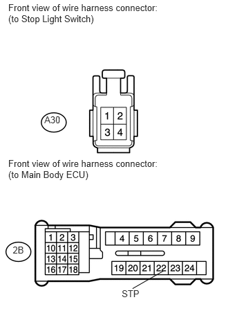
Disconnect the 2B ECU connector.
Measure the voltage according to the value(s) in the table below.
- Standard Voltage:
Tester Connection Condition Specified Condition 2B-22 (STP) - Body ground Brake pedal depressed 11 to 14 V Brake pedal released Below 1 V
Measure the resistance according to the value(s) in the table below.
- Standard Resistance:
Tester Connection Condition Specified Condition 2B-22 (STP) - A30-1 Always Below 1 Ω A30-1 - Body ground Always 10 kΩ or higher
OK
NG