WINCH WINCH UNIT INSTALLATION
PROCEDURE

 38110
1.INSTALL WINCH ASSEMBLY
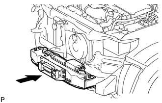
Using a crane or equivalent, install the winch assembly.
- CAUTION:
-
Be careful as the winch assembly is very heavy.
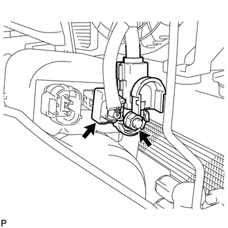
Connect the wire with the nut.
- Torque:
- 9.3 N*m (95 kgf*cm, 83 in.*lbf)
Connect the connector.
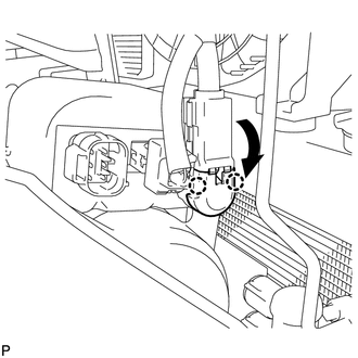
Move the cover in the direction indicated by the arrow shown in the illustration and attach the 2 claws.
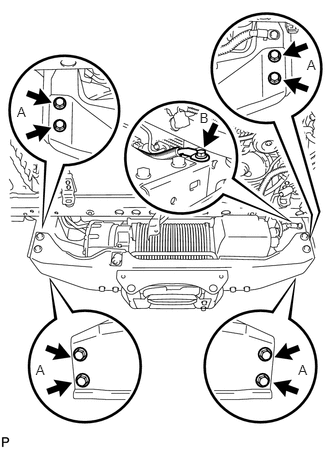
Install the mounting bracket with the 9 bolts.
- Torque:
- for bolt A : 33 N*m (336 kgf*cm, 24 ft.*lbf)
- for bolt B : 19 N*m (194 kgf*cm, 15 ft.*lbf)
38649
2.INSTALL WINCH CONTROL WIRE
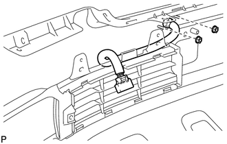
Install the winch control wire with the 2 nuts.
- Torque:
- 5 N*m (51 kgf*cm, 45 in.*lbf)
32917
3.INSTALL TRANSMISSION OIL COOLER AIR DUCT (w/ Oil Cooler)
53294C
4.INSTALL RADIATOR SIDE DEFLECTOR LH
53293C
5.INSTALL RADIATOR SIDE DEFLECTOR RH (w/o Oil Cooler)
52521
6.INSTALL FRONT UPPER CENTER BUMPER RETAINER
81150
7.INSTALL HEADLIGHT ASSEMBLY LH
81110
8.INSTALL HEADLIGHT ASSEMBLY RH
52113D
9.INSTALL FRONT BUMPER EXTENSION LH
52112D
10.INSTALL FRONT BUMPER EXTENSION RH
52119A
11.INSTALL FRONT BUMPER COVER
53111
12.INSTALL RADIATOR GRILLE ASSEMBLY
52049
13.INSTALL FRONT BUMPER WINCH COVER SUB-ASSEMBLY
53292A
14.INSTALL UPPER RADIATOR SUPPORT SEAL
53806
15.INSTALL FRONT FENDER SPLASH SHIELD SUB-ASSEMBLY LH
53805
16.INSTALL FRONT FENDER SPLASH SHIELD SUB-ASSEMBLY RH
17.CONNECT CABLE TO NEGATIVE BATTERY TERMINAL
- NOTICE:
-
When disconnecting the cable, some systems need to be initialized after the cable is reconnected (See page General>INTRODUCTION>REPAIR INSTRUCTION>INITIALIZATION).