1VD-FTV COOLING RADIATOR INSTALLATION
PROCEDURE

 16400
1.INSTALL RADIATOR ASSEMBLY
Install the radiator with the 4 bolts.
- Torque:
- 18 N*m (184 kgf*cm, 13 ft.*lbf)
16371
2.INSTALL FAN PULLEY
16711
3.INSTALL FAN SHROUD WITH FAN
32942
4.INSTALL OIL COOLER TUBE (for Automatic Transmission)
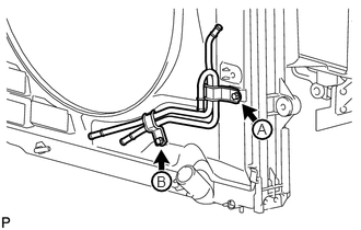
Temporarily install the oil cooler tube to the fan shroud with the bolt labeled A. Install the bolt labeled B. Then tighten the bolt labeled A to the specified torque.
- Torque:
- 5.0 N*m (51 kgf*cm, 44 in.*lbf)
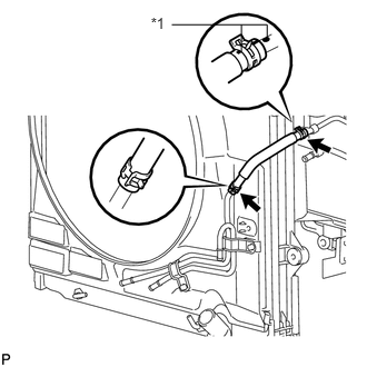
Connect the inlet No. 4 oil cooler hose as shown in the illustration.
| *1 | Paint Mark |
- NOTICE:
-
Make sure the pinching portion of each clip is facing the direction shown in the illustration.
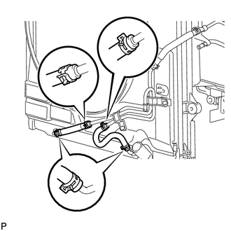
Connect the inlet No. 2 and No. 3 oil cooler hoses as shown in the illustration.
- NOTICE:
-
Make sure the pinching portion of each clip is facing the direction shown in the illustration.
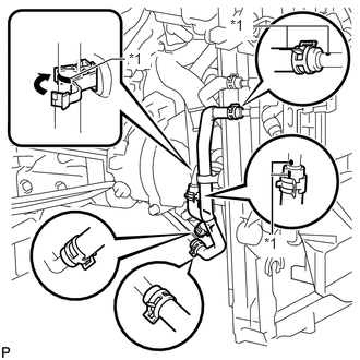
Connect the inlet and outlet No. 1 oil cooler hoses as shown in the illustration.
| *1 | Paint Mark |
- NOTICE:
-
Make sure the pinching portion of each clip is facing the direction shown in the illustration.
Pass the hose through the flexible hose clamp and close the clamp shown in the illustration.
16361A
5.INSTALL V-RIBBED BELT
6.INSTALL NO. 3 IDLER PULLEY (w/ Viscous Heater)
7.INSTALL NO. 1 IDLER PULLEY (w/ Viscous Heater)
8.INSTALL V-RIBBED BELT (w/ Viscous Heater)
16572D
9.CONNECT NO. 2 RADIATOR HOSE
16571C
10.CONNECT NO. 1 RADIATOR HOSE
16470
11.INSTALL RADIATOR RESERVOIR ASSEMBLY
44369A
12.INSTALL NO. 1 OIL RESERVOIR BRACKET
44360
13.INSTALL VANE PUMP OIL RESERVOIR ASSEMBLY
17861
14.INSTALL INTAKE AIR CONNECTOR
17881
15.TEMPORARILY INSTALL NO. 1 AIR CLEANER HOSE
17705
16.INSTALL AIR CLEANER CAP SUB-ASSEMBLY
12601E
17.INSTALL NO. 1 ENGINE COVER SUB-ASSEMBLY (w/ Intercooler)
82113
18.INSTALL NO. 3 ENGINE ROOM WIRE
28800
19.CONNECT CABLE TO NEGATIVE BATTERY TERMINAL
- NOTICE:
-
When disconnecting the cable, some systems need to be initialized after the cable is reconnected (See page General>INTRODUCTION>REPAIR INSTRUCTION>INITIALIZATION).
Connect the cables to negative (-) main battery and sub-battery terminals.
20.ADD ENGINE COOLANT
21.INSPECT FOR ENGINE COOLANT LEAK
53294C
22.INSTALL RADIATOR SIDE DEFLECTOR LH
Install the side deflector with the 4 clips.
53293C
23.INSTALL RADIATOR SIDE DEFLECTOR RH (for Manual Transmission)
Install the deflector with the 4 clips.
32917
24.INSTALL TRANSMISSION OIL COOLER AIR DUCT (for Automatic Transmission)
Install the oil cooler air duct with the 4 bolts.
- Torque:
- 4.9 N*m (50 kgf*cm, 43 in.*lbf)
52119A
25.INSTALL FRONT BUMPER COVER
for Standard: (See page Vehicle Exterior>EXTERIOR PANELS / TRIM>FRONT BUMPER(for Standard)>INSTALLATION)
w/ Winch: (See page Vehicle Exterior>EXTERIOR PANELS / TRIM>FRONT BUMPER(w/ Winch)>INSTALLATION)
53111
26.INSTALL RADIATOR GRILLE
52049
27.INSTALL FRONT BUMPER WINCH COVER (w/ Winch)
53292A
28.INSTALL UPPER RADIATOR SUPPORT SEAL
53736G
29.INSTALL FRONT FENDER APRON SEAL FRONT RH
30.INSTALL FRONT WHEEL RH
51405A
31.INSTALL NO. 1 ENGINE UNDER COVER SUB-ASSEMBLY
53805
32.INSTALL FRONT FENDER SPLASH SHIELD SUB-ASSEMBLY RH
53806
33.INSTALL FRONT FENDER SPLASH SHIELD SUB-ASSEMBLY LH