EXTERIOR PANELS / TRIM REAR BUMPER(w/ Pintle Hook) REMOVAL
CAUTION / NOTICE / HINT
- HINT:
-
If the bumper is damaged, there is a possibility that the installation area of the blind spot monitor sensor may be deformed and the blind spot monitor system may not operate correctly, so visually inspect the blind spot monitor sensor installation area (frame, stud bolt) to make sure it is not dented or bent.
-
Click hereAudio / Visual / Telematics>PARK ASSIST / MONITORING>BLIND SPOT MONITOR SYSTEM>OPERATION CHECK
-
If the visual inspection finds a problem, check the installation condition of the blind spot monitor sensor, and adjust the installation position of the blind spot monitor sensor as necessary.
PROCEDURE

 51980A
1.REMOVE PINTLE HOOK ASSEMBLY
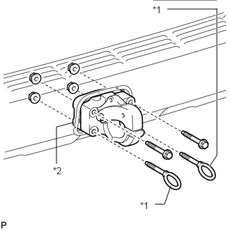
For vehicles with a spare tire installed to the underbody, remove the spare tire.
| *1 | Eyelet Pintle Hook |
| *2 | Pintle Hook Bracket |
Remove the 4 nuts.
Remove the 2 bolts, 2 eyelet pintle hooks, pintle hook assembly and pintle hook bracket.
51937C
2.REMOVE SPARE WHEEL CARRIER HINGE BRACKET (w/ Tire Carrier)
51902A
3.REMOVE SPARE WHEEL COVER SUB-ASSEMBLY (w/ Tire Carrier)
51903B
4.REMOVE SPARE WHEEL CARRIER SUB-ASSEMBLY (w/ Tire Carrier)
76626E
5.REMOVE REAR QUARTER PANEL MUDGUARD LH
76625G
6.REMOVE REAR QUARTER PANEL MUDGUARD RH
52162B
7.REMOVE REAR BUMPER NO. 1 PLATE (for Step)
Put protective tape around the rear bumper No. 1 plate.
Detach the 20 claws and remove the rear bumper No. 1 plate.
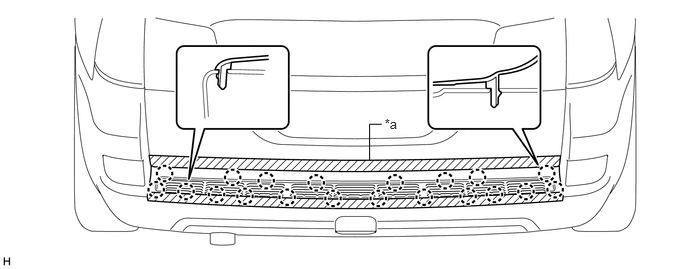
| *a | Protective Tape | - | - |
52159
8.REMOVE REAR BUMPER COVER
- HINT:
-
For the rear bumper cover with tire carrier, use the procedures described below.
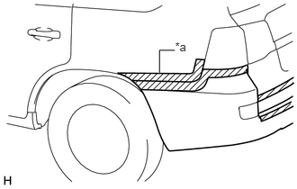
Put protective tape around the rear bumper cover.
- HINT:
-
Use the same procedure for the other side.
| *a | Protective Tape |
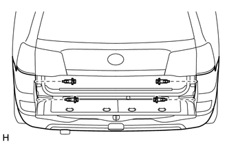
Open the tail gate and remove the 4 clips.
Close the tail gate.
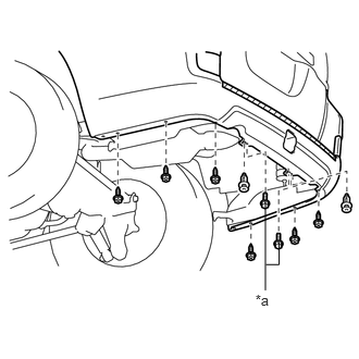
Remove the 2 bolts, 6 screws and 2 clips.
| *a | Bolt |
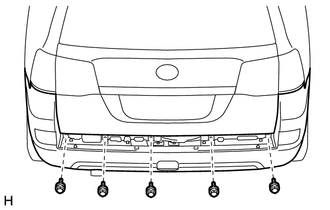
Remove the 5 bolts.
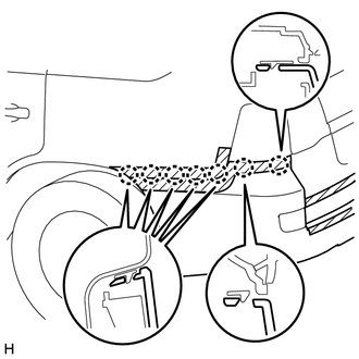
Detach the 7 claws.
- HINT:
-
Use the same procedure for the other side.
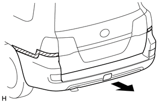
Remove the rear bumper cover.
w/ TOYOTA Parking Assist-sensor System or w/ Rear Fog Light:
Disconnect the No. 2 frame wire connector.
58724B
9.REMOVE NO. 2 LUGGAGE COMPARTMENT SIDE COVER PROTECTOR
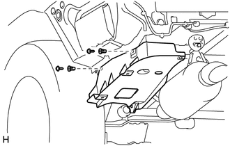
Remove the 2 screws, 2 grommets and No. 2 luggage compartment side cover protector.
58723B
10.REMOVE NO. 1 LUGGAGE COMPARTMENT SIDE COVER PROTECTOR
- HINT:
-
Use the same procedure described for the LH side.
81560
11.REMOVE REAR COMBINATION LIGHT ASSEMBLY LH
81550
12.REMOVE REAR COMBINATION LIGHT ASSEMBLY RH
- HINT:
-
Use the same procedure described for the LH side.
52563D
13.REMOVE REAR BUMPER UPPER RETAINER LH
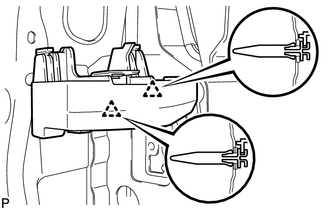
Detach the 2 clips and remove the rear bumper upper retainer LH.
52562E
14.REMOVE REAR BUMPER UPPER RETAINER RH
- HINT:
-
Use the same procedure described for the LH side.
52156A
15.REMOVE REAR BUMPER SIDE SUPPORT LH
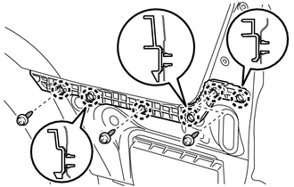
Remove the 3 screws.
Detach the 6 claws and remove the rear bumper side support LH.
52155A
16.REMOVE REAR BUMPER SIDE SUPPORT RH
- HINT:
-
Use the same procedure described for the LH side.
52172B
17.REMOVE REAR BUMPER NO. 2 REINFORCEMENT
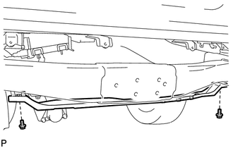
Remove the 2 bolts and rear bumper No. 2 reinforcement.
57615C
18.REMOVE REAR BUMPER ARM BRACKET
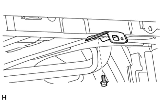
Remove the bolt and rear bumper arm bracket.
- HINT:
-
Use the same procedure for both rear bumper arm brackets.
57616B
19.REMOVE REAR BUMPER ARM BRACKET LH
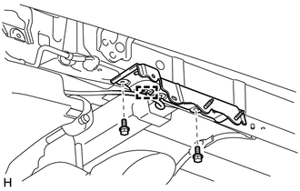
Detach the clamp.
Remove the 2 bolts and rear bumper arm bracket LH.