Home › Engine / Hybrid System › 3UR-FE (ENGINE CONTROL) › SFI SYSTEM(w/ Secondary Air Injection System) › from 2017.08
RM2660E _51 Engine / Hybrid System _052775 3UR-FE ENGINE CONTROL _0327320 SFI SYSTEM(w/ Secondary Air Injection System) C

3UR-FE ENGINE CONTROL  SFI SYSTEM(w/ Secondary Air Injection System)  P0412  Secondary Air Injection System Switching Valve "A" Circuit  P0415  Secondary Air Injection System Switching Valve "B" Circuit  


DESCRIPTION

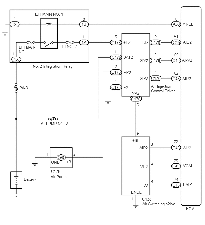
The Secondary Air Injection (AIR) system consists of an air pump, the Air Switching Valve (ASV), a pressure sensor, the Air Injection Control Driver (AID) and the ECM. For a short time after a cold engine start, the AIR system pumps secondary air to the exhaust port of the cylinder head to purify the exhaust emissions. The secondary air is supplied by the air pump and is pumped to the exhaust port through the ASV.

The AID drives the ASV and the air pump according to command signals transmitted by the ECM. The pressure sensor detects the pressure in the secondary air passage when the AIR system is ON and OFF, and transmits a pressure signal to the ECM.

The AID is not only equipped to drive the pump and valve, but also with a diagnosis function to detect malfunctions in the AIR system circuit.

HINT:

As a large current is required to drive the air pump and ASV, an AID is installed to this system.
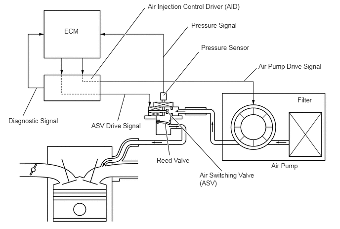

A162565E05
0.771,1.854 0.479,2.448 false 3.958,0.563 3.438,1.208 false 3.573,3.271 3.479,2.594 true 2.479,2.552 2.635,1.979 false 3.521,2.344 4.677,3.604 true 5.406,1.438 5.146,1.708 false 3.448,2.01 4.188,1.094 true 1.927,1.656 3.052,0.167 true 1.354,0.573 1.708,0.74 0.354,0.167 10 false ECM 3.115,0.052 5.135,0.26 2.021,0.208 10 false Air Injection Control Driver (AID) 0.177,2.458 1.354,2.656 1.177,0.198 10 false Diagnostic Signal 4.031,0.448 5.083,0.635 1.052,0.188 10 false Pressure Signal 3.302,3.292 4.073,3.469 0.771,0.177 10 false Reed Valve 1.927,2.563 3.042,2.75 1.115,0.188 10 false ASV Drive Signal 4.208,3.604 5.427,3.969 1.219,0.365 10 false Air Switching Valve (ASV) 5.719,3.406 6.333,3.604 0.615,0.198 10 false Air Pump 6.271,2.021 6.635,2.208 0.365,0.188 10 false Filter 5.448,1.313 6.875,1.51 1.427,0.198 10 false Air Pump Drive Signal 4.24,0.917 5.365,1.125 1.125,0.208 10 false Pressure Sensor

DTC Code DTC Detection Condition Trouble Area
P0412
P0415

After a cold engine start, all of the following conditions are met (1 trip detection logic):

(a)

The Secondary Air Injection (AIR) system is not operating (air pump OFF, Air Switching Valve [ASV] OFF).

(b)

The diagnostic signal from the Air Injection Control Driver (AID) is 40%.

(c)

The battery voltage is 8 V or higher.


·

Open in Air Switching Valve (ASV) drive circuit

·

Air Injection Control Driver (AID)

·

Air Switching Valve (ASV)

·

ECM


P0412
P0415

After a cold engine start, all of the following conditions are met (1 trip detection logic):

(a)

The Secondary Air Injection (AIR) system is operating (air pump ON, Air Switching Valve [ASV] ON).

(b)

The diagnostic signal from the Air Injection Control Driver (AID) is 40%.

(c)

The battery voltage is 8 V or higher.


·

Short between ASV drive circuit and body ground

·

AID

·

ASV

·

ECM


MONITOR DESCRIPTION

The Air Injection Control Driver (AID) detects open and short circuits according to the voltages of the air pump terminal (VP) and the Air Switching Valve (ASV) terminal (VV), and transmits diagnostic information as a signal to the ECM.

For a short time after a cold engine start, the ECM transmits command signals to the AID to drive the air pump and ASV.

The AID transmits an ASV malfunction signal to the ECM if either of the following conditions is met:

·

The voltage at the AID terminal relating to the ASV is low despite the AID receiving command signals from the ECM to drive the ASV.

·

The voltage at the AID terminal relating to the ASV is high despite the AID receiving no command signals from the ECM to drive the ASV.


The ECM stores the DTC based on diagnostic signals from the AID.

WIRING DIAGRAM
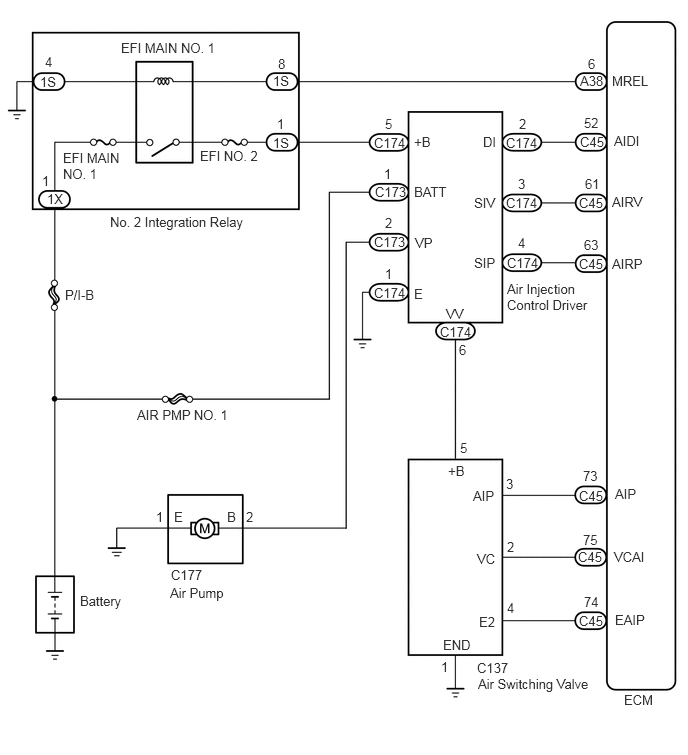
for Bank 1:
A411084E01
5.271,1.406 5.885,1.604 0.615,0.198 10 false C174 5.271,2.031 5.885,2.229 0.615,0.198 10 false C174 5.281,2.656 5.896,2.854 0.615,0.198 10 false C174 3.896,1.406 4.51,1.604 0.615,0.198 10 false C174 3.896,2.969 4.51,3.167 0.615,0.198 10 false C174 4.583,3.375 5.198,3.573 0.615,0.198 10 false C174 5.281,2.927 6.177,3.646 0.896,0.719 10 false Air Injection Control Driver 4.979,7.042 6.271,7.26 1.292,0.219 10 false Air Switching Valve 4.969,6.875 6.26,7.094 1.292,0.219 10 false C137 3.906,1.917 5.198,2.135 1.292,0.219 10 false C173 3.896,2.438 5.188,2.656 1.292,0.219 10 false C173 4.313,1.396 4.927,1.594 0.615,0.198 10 false +B 4.313,1.917 4.927,2.115 0.615,0.198 10 false BATT 4.323,2.448 4.938,2.646 0.615,0.198 10 false VP 4.313,2.979 4.927,3.177 0.615,0.198 10 false E 5.031,1.396 5.646,1.594 0.615,0.198 10 false DI 4.938,2.031 5.552,2.229 0.615,0.198 10 false SIV 4.938,2.656 5.552,2.854 0.615,0.198 10 false SIP 6.375,0.76 6.99,0.958 0.615,0.198 10 false MREL 6.396,1.385 7.01,1.583 0.615,0.198 10 false AIDI 6.375,2.021 6.99,2.219 0.615,0.198 10 false AIRV 6.375,2.667 6.99,2.865 0.615,0.198 10 false AIRP 6.042,0.76 6.656,0.958 0.615,0.198 10 false A38 2.844,0.76 3.458,0.958 0.615,0.198 10 false 1S 2.844,1.406 3.458,1.604 0.615,0.198 10 false 1S 0.417,0.771 1.031,0.969 0.615,0.198 10 false 1S 0.49,1.99 1.104,2.188 0.615,0.198 10 false 1X 6.042,1.396 6.656,1.594 0.615,0.198 10 false C45 6.031,2.031 6.646,2.229 0.615,0.198 10 false C45 6.031,2.667 6.646,2.865 0.615,0.198 10 false C45 6.031,5.083 6.646,5.281 0.615,0.198 10 false C45 6.021,5.719 6.635,5.917 0.615,0.198 10 false C45 6.031,6.385 6.646,6.583 0.615,0.198 10 false C45 1.771,6.094 2.458,6.354 0.688,0.26 10 false Air Pump 1.781,5.906 2.469,6.167 0.688,0.26 10 false C177 0.833,6.177 1.521,6.438 0.688,0.26 10 false Battery 1.427,4.24 2.531,4.448 1.104,0.208 10 false AIR PMP NO. 1 0.677,2.99 1.781,3.198 1.104,0.208 10 false P/I-B 1.146,2.229 3.01,2.427 1.865,0.198 10 false No. 2 Integration Relay 1.26,0.417 2.354,0.615 1.094,0.198 10 false EFI MAIN NO. 1 0.656,1.563 1.333,1.927 0.677,0.365 10 false EFI MAIN NO. 1 2.083,1.542 2.802,1.75 0.719,0.208 10 false EFI NO. 2 2.896,0.583 3.177,0.781 0.281,0.198 10 false 8 2.885,1.208 3.167,1.406 0.281,0.198 10 false 1 0.469,0.563 0.75,0.76 0.281,0.198 10 false 4 0.438,1.802 0.719,2 0.281,0.198 10 false 1 4.01,1.208 4.292,1.406 0.281,0.198 10 false 5 4,1.729 4.281,1.927 0.281,0.198 10 false 1 4.01,2.771 4.292,2.969 0.281,0.198 10 false 1 4.01,2.24 4.292,2.438 0.281,0.198 10 false 2 5.406,1.208 5.688,1.406 0.281,0.198 10 false 2 5.396,2.448 5.677,2.646 0.281,0.198 10 false 4 5.396,1.833 5.677,2.031 0.281,0.198 10 false 3 6.125,0.583 6.406,0.781 0.281,0.198 10 false 6 6.083,1.198 6.365,1.396 0.281,0.198 10 false 52 6.094,1.833 6.375,2.031 0.281,0.198 10 false 61 6.083,2.469 6.365,2.667 0.281,0.198 10 false 63 6.073,4.875 6.354,5.073 0.281,0.198 10 false 73 6.073,5.542 6.354,5.74 0.281,0.198 10 false 75 6.083,6.188 6.365,6.385 0.281,0.198 10 false 74 5.271,4.958 5.552,5.156 0.281,0.198 10 false 3 5.281,6.25 5.563,6.448 0.281,0.198 10 false 4 5.281,5.615 5.563,5.813 0.281,0.198 10 false 2 4.927,5.083 5.542,5.281 0.615,0.198 10 false AIP 4.969,5.74 5.583,5.938 0.615,0.198 10 false VC 4.99,6.396 5.604,6.594 0.615,0.198 10 false E2 4.615,6.635 5.229,6.833 0.615,0.198 10 false END 4.594,6.865 4.875,7.063 0.281,0.198 10 false 1 4.792,4.583 5.073,4.781 0.281,0.198 10 false 5 4.667,4.823 5.281,5.021 0.615,0.198 10 false +B 2.563,5.302 2.844,5.5 0.281,0.198 10 false 2 1.625,5.302 1.906,5.5 0.281,0.198 10 false 1 2.365,5.302 2.979,5.5 0.615,0.198 10 false B 1.813,5.302 2.427,5.5 0.615,0.198 10 false E 6.5,7.208 6.948,7.448 0.448,0.24 10 false ECM 6.406,5.063 7.021,5.26 0.615,0.198 10 false AIP 6.396,5.719 7.01,5.917 0.615,0.198 10 false VCAI 6.406,6.375 7.021,6.573 0.615,0.198 10 false EAIP 4.646,3.188 5.26,3.385 0.615,0.198 10 false VV 4.781,3.563 5.063,3.76 0.281,0.198 10 false 6

for Bank 2:
A411084E02
5.271,1.406 5.885,1.604 0.615,0.198 10 false C176 5.271,2.031 5.885,2.229 0.615,0.198 10 false C176 5.281,2.656 5.896,2.854 0.615,0.198 10 false C176 3.896,1.406 4.51,1.604 0.615,0.198 10 false C176 3.896,2.969 4.51,3.167 0.615,0.198 10 false C176 4.583,3.375 5.198,3.573 0.615,0.198 10 false C176 5.281,2.927 6.177,3.646 0.896,0.719 10 false Air Injection Control Driver 4.979,7.042 6.271,7.26 1.292,0.219 10 false Air Switching Valve 4.969,6.875 6.26,7.094 1.292,0.219 10 false C138 3.906,1.917 5.198,2.135 1.292,0.219 10 false C175 3.896,2.438 5.188,2.656 1.292,0.219 10 false C175 4.313,1.396 4.927,1.594 0.615,0.198 10 false +B2 4.313,1.917 4.927,2.115 0.615,0.198 10 false BAT2 4.323,2.448 4.938,2.646 0.615,0.198 10 false VP2 4.313,2.979 4.927,3.177 0.615,0.198 10 false E2 4.979,1.396 5.594,1.594 0.615,0.198 10 false DI2 4.885,2.031 5.5,2.229 0.615,0.198 10 false SIV2 4.885,2.656 5.5,2.854 0.615,0.198 10 false SIP2 6.375,0.76 6.99,0.958 0.615,0.198 10 false MREL 6.396,1.385 7.01,1.583 0.615,0.198 10 false AID2 6.365,2.021 6.979,2.219 0.615,0.198 10 false ARV2 6.375,2.667 6.99,2.865 0.615,0.198 10 false AIR2 6.042,0.76 6.656,0.958 0.615,0.198 10 false A38 2.844,0.76 3.458,0.958 0.615,0.198 10 false 1S 2.844,1.406 3.458,1.604 0.615,0.198 10 false 1S 0.417,0.771 1.031,0.969 0.615,0.198 10 false 1S 0.49,1.99 1.104,2.188 0.615,0.198 10 false 1X 6.042,1.396 6.656,1.594 0.615,0.198 10 false C45 6.031,2.031 6.646,2.229 0.615,0.198 10 false C45 6.031,2.667 6.646,2.865 0.615,0.198 10 false C45 6.031,5.083 6.646,5.281 0.615,0.198 10 false C45 6.021,5.719 6.635,5.917 0.615,0.198 10 false C45 6.031,6.385 6.646,6.583 0.615,0.198 10 false C45 1.771,6.094 2.458,6.354 0.688,0.26 10 false Air Pump 1.781,5.906 2.469,6.167 0.688,0.26 10 false C178 0.833,6.177 1.521,6.438 0.688,0.26 10 false Battery 1.427,4.24 2.531,4.448 1.104,0.208 10 false AIR PMP NO. 2 0.677,2.99 1.781,3.198 1.104,0.208 10 false P/I-B 1.146,2.229 3.01,2.427 1.865,0.198 10 false No. 2 Integration Relay 1.229,0.417 2.323,0.615 1.094,0.198 10 false EFI MAIN NO. 1 0.656,1.563 1.333,1.927 0.677,0.365 10 false EFI MAIN NO. 1 2.083,1.542 2.802,1.75 0.719,0.208 10 false EFI NO. 2 2.896,0.583 3.177,0.781 0.281,0.198 10 false 8 2.885,1.208 3.167,1.406 0.281,0.198 10 false 1 0.469,0.563 0.75,0.76 0.281,0.198 10 false 4 0.438,1.802 0.719,2 0.281,0.198 10 false 1 4.01,1.208 4.292,1.406 0.281,0.198 10 false 5 4,1.729 4.281,1.927 0.281,0.198 10 false 1 4.01,2.771 4.292,2.969 0.281,0.198 10 false 1 4.01,2.24 4.292,2.438 0.281,0.198 10 false 2 5.406,1.208 5.688,1.406 0.281,0.198 10 false 2 5.396,2.448 5.677,2.646 0.281,0.198 10 false 4 5.396,1.833 5.677,2.031 0.281,0.198 10 false 3 6.125,0.583 6.406,0.781 0.281,0.198 10 false 6 6.083,1.198 6.365,1.396 0.281,0.198 10 false 51 6.094,1.833 6.375,2.031 0.281,0.198 10 false 60 6.083,2.469 6.365,2.667 0.281,0.198 10 false 62 6.073,4.875 6.354,5.073 0.281,0.198 10 false 72 6.073,5.542 6.354,5.74 0.281,0.198 10 false 75 6.083,6.188 6.365,6.385 0.281,0.198 10 false 74 5.271,4.958 5.552,5.156 0.281,0.198 10 false 3 5.281,6.25 5.563,6.448 0.281,0.198 10 false 4 5.281,5.615 5.563,5.813 0.281,0.198 10 false 2 4.875,5.083 5.49,5.281 0.615,0.198 10 false AIP2 4.906,5.74 5.521,5.938 0.615,0.198 10 false VC2 4.938,6.396 5.552,6.594 0.615,0.198 10 false E22 4.583,6.635 5.198,6.833 0.615,0.198 10 false ENDL 4.594,6.865 4.875,7.063 0.281,0.198 10 false 1 4.792,4.583 5.073,4.781 0.281,0.198 10 false 5 4.625,4.823 5.24,5.021 0.615,0.198 10 false +BL 2.563,5.302 2.844,5.5 0.281,0.198 10 false 2 1.625,5.302 1.906,5.5 0.281,0.198 10 false 1 2.313,5.573 2.927,5.771 0.615,0.198 10 false +B 1.781,5.583 2.396,5.781 0.615,0.198 10 false GND 6.5,7.208 6.948,7.448 0.448,0.24 10 false ECM 6.396,5.073 7.01,5.271 0.615,0.198 10 false AIP2 6.396,5.708 7.01,5.906 0.615,0.198 10 false VCAI 6.396,6.365 7.01,6.563 0.615,0.198 10 false EAIP 4.781,3.583 5.063,3.781 0.281,0.198 10 false 6 4.615,3.177 5.229,3.375 0.615,0.198 10 false VV2

CAUTION / NOTICE / HINT

HINT:
·

By using the intelligent tester to perform the Secondary Air Injection Check operation in the Utility, the air-fuel ratio and the pressure in the secondary air injection system passage can be checked while the secondary air injection system is operating. This helps technicians to troubleshoot the system when it malfunctions.

·

Read freeze frame data using the intelligent tester. Freeze frame data records the engine condition when malfunctions are detected. When troubleshooting, freeze frame data can help determine if the vehicle was moving or stationary, if the engine was warmed up or not, if the air-fuel ratio was lean or rich, and other data from the time the malfunction occurred.


PROCEDURE
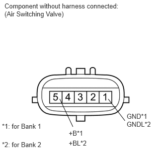
1.INSPECT AIR SWITCHING VALVE ASSEMBLY
A160404E06
0.094,0.038 2.583,0.402 2.489,0.364 10 Component without harness connected: (Air Switching Valve) 0.042,2.56 0.962,2.729 0.920,0.170 10 *1: for Bank 1 0.042,2.946 0.927,3.116 0.885,0.170 10 *2: for Bank 2 1.441,2.712 1.903,2.861 0.461,0.149 10 +B*1 1.441,2.918 1.861,3.067 0.420,0.149 10 +BL*2 1.527,2.656 1.252,2.074 false 2.268,2.074 2.618,2.53 false 2.655,2.354 3.227,2.683 0.573,0.330 10 GND*1 GNDL*2

a.

Disconnect the air switching valve (ASV) connector.


b.

Measure the resistance according to the value(s) in the table below.

Standard Resistance:
Tester Connection Condition Specified Condition
C137-5 (+B) - C137-1 (GND) 20°C (68°F) 4.5 to 5.5 Ω
C138-5 (+BL) - C138-1 (GNDL) 20°C (68°F) 4.5 to 5.5 Ω


OK

2.CHECK HARNESS AND CONNECTOR (AIR SWITCHING VALVE - BODY GROUND)

NG

2.CHECK HARNESS AND CONNECTOR (AIR SWITCHING VALVE - BODY GROUND)
a.

Disconnect the ASV connector.


b.

Measure the resistance according to the value(s) in the table below.

Standard Resistance:
Tester Connection Condition Specified Condition
C137-1 (GND) - Body ground Always Below 1 Ω
C138-1 (GNDL) - Body ground Always Below 1 Ω


OK

3.CHECK HARNESS AND CONNECTOR (AIR SWITCHING VALVE - AIR INJECTION CONTROL DRIVER)

NG

REPAIR OR REPLACE HARNESS OR CONNECTOR

3.CHECK HARNESS AND CONNECTOR (AIR SWITCHING VALVE - AIR INJECTION CONTROL DRIVER)
a.

Disconnect the ASV connector.


b.

Disconnect the AID connector.


c.

Measure the resistance according to the value(s) in the table below.

Standard Resistance:
Tester Connection Condition Specified Condition
C137-5 (+B) - C174-6 (VV) Always Below 1 Ω
C138-5 (+BL) - C176-6 (VV2) Always Below 1 Ω
C137-5 (+B) or C174-6 (VV) - Body ground Always 10 kΩ or higher
C138-5 (+BL) or C176-6 (VV2) - Body ground Always 10 kΩ or higher


OK

NG

REPAIR OR REPLACE HARNESS OR CONNECTOR