AE80F AUTOMATIC TRANSMISSION / TRANSAXLE AUTOMATIC TRANSMISSION SYSTEM P0776 Pressure Control Solenoid "B" Performance or Stuck OFF
DESCRIPTION
Based on signals from the transmission revolution sensors (NT and SP2), the actual gear is detected.
If the detected gear is different than the commanded gear, the TCM detects related mechanical problems in the shift solenoid valves, transmission valve body assembly and automatic transmission assembly (clutch, brake, gear, etc.).
- HINT:
-
Actual gear when a problem occurs in shift solenoid valve SL2 (without fail-safe control):
TCM commanded gear 1st 2nd 3rd 4th 5th 6th 7th 8th Actual gear during SL2 stuck ON malfunction 1st 2nd 3rd 4th N* N* N* N* Actual gear during SL2 stuck OFF malfunction 5th 8th 7th 6th 5th 6th 7th 8th
-
*: Neutral
| DTC No. | DTC Detection Condition
1.
Diagnosis Condition 2.
Malfunction Status 3.
Malfunction Time 4.
Other |
Trouble Area |
|---|---|---|
| P0776 | SL2 stuck ON malfunction:
1.
Battery voltage is 9.5 V or higher, engine speed is more than 400 rpm, and the vehicle is driven with the shift lever in D (no malfunctions are detected in shift solenoid valve SC1, SC2, SL1, SL2, SL3, SL4, SL5, SLT, SLU, park/neutral position switch assembly, TCM, electronic throttle, knock control sensor, No. 1 ATF temperature sensor, transmission revolution sensors (NT), and CAN communication system) 2.
When the TCM commands the transmission to shift to 5th to 8th, the engine overruns (neutral status). 3.
Malfunction status is detected 5 times per trip 4.
2 trip detection logic |
·
Shift solenoid valve SL1 ·
Shift solenoid valve SL2 ·
Shift solenoid valve SL3 ·
Shift solenoid valve SL4 ·
Shift solenoid valve SL5 ·
Shift solenoid valve SLT ·
Transmission valve body assembly ·
Automatic transmission assembly (clutch, brake, gear, etc.) |
| SL2 stuck OFF malfunction:
1.
Battery voltage is 9.5 V or higher, engine speed is more than 400 rpm, and the vehicle is driven with the shift lever in D (no malfunctions are detected in shift solenoid valve SC1, SC2, SL1, SL2, SL3, SL4, SL5, SLT, SLU, park/neutral position switch assembly, TCM, electronic throttle, knock control sensor, No. 1 ATF temperature sensor, transmission revolution sensors (NT), and CAN communication system) 2.
One of following occurs: (a) When the TCM commands the transmission to shift to 1st the actual gear changes to 5th gear. (b) When the TCM commands the transmission to shift to 2nd the actual gear changes to 8th gear. (c) When the TCM commands the transmission to shift to 3rd the actual gear changes to 7th gear. (d) When the TCM commands the transmission to shift to 4th the actual gear changes to 6th gear. 3.
Malfunction status is detected 5 times per trip 4.
2 trip detection logic |
·
Shift solenoid valve SL2 ·
Transmission valve body assembly ·
Automatic transmission assembly (clutch, brake, gear, etc.) |
MONITOR DESCRIPTION
The TCM commands gear shifts by turning the shift solenoid valves on and off. According to the input shaft speed and output shaft speed, the TCM detects the actual gear (1st, 2nd, 3rd, 4th, 5th, 6th, 7th or 8th gear position). When the gear commanded by the TCM and the actual gear are not the same, the TCM illuminates the MIL* and stores this DTC.
*: w/ OBD
CAUTION / NOTICE / HINT
- NOTICE:
-
Perform registration and/or initialization when parts related to the automatic transmission are replaced (See page Drivetrain>AE80F (AUTOMATIC TRANSMISSION / TRANSAXLE)>AUTOMATIC TRANSMISSION SYSTEM>INITIALIZATION).
- HINT:
-
After performing repair, clear the DTCs and perform the following procedure to check that DTCs are not output.
- 1.
Perform the D Position Shift Test in Road Test (See page Drivetrain>AE80F (AUTOMATIC TRANSMISSION / TRANSAXLE)>AUTOMATIC TRANSMISSION SYSTEM>ROAD TEST).*1
2.Turn the engine switch off.
3.Perform step (*1) again.
4.Check for DTCs again (See page Drivetrain>AE80F (AUTOMATIC TRANSMISSION / TRANSAXLE)>AUTOMATIC TRANSMISSION SYSTEM>DTC CHECK / CLEAR).
PROCEDURE
Connect the GTS to the DLC3.
Turn the engine switch on (IG).
Turn the GTS on.
Enter the following menus: Powertrain / ECT / Trouble Codes.
Read the DTCs using the GTS.
| Result | Proceed to |
|---|---|
| DTC P0776 and DTC P0746, P076B, P076C, P0796, P08CD, P08CE, P2714, P2808 and/or P2817 are output | A |
| Only DTC P0776 is output | B |
| DTCs other than P0746, P076B, P076C, P0776, P0796, P08CD, P08CE, P2714, P2808 and P2817 are also output | C |
- HINT:
-
If DTCs other than P0746, P076B, P076C, P0776, P0796, P08CD, P08CE, P2714, P2808 and P2817 are output, perform troubleshooting for those DTCs first.
A
B
C
Clear the DTCs (See page Drivetrain>AE80F (AUTOMATIC TRANSMISSION / TRANSAXLE)>AUTOMATIC TRANSMISSION SYSTEM>DTC CHECK / CLEAR).
- HINT:
-
Write down the currently output DTCs before clearing them.
Perform the stall speed test (See page Drivetrain>AE80F (AUTOMATIC TRANSMISSION / TRANSAXLE)>AUTOMATIC TRANSMISSION SYSTEM>MECHANICAL SYSTEM TESTS).
| Test Condition | Proceed to |
|---|---|
| Stall speed test can be performed | A |
| Stall speed test cannot be performed | B |
A
B
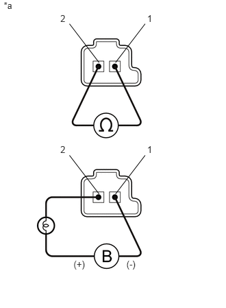
Remove the shift solenoid valve SL1, SL2, SL3, SL4 and SL5 (See page Drivetrain>AE80F (AUTOMATIC TRANSMISSION / TRANSAXLE)>VALVE BODY ASSEMBLY>DISASSEMBLY).
Measure the resistance according to the value(s) in the table below.
- Standard Resistance:
Tester Connection Condition Specified Condition Terminal 1 of the shift solenoid valve SL1 - Terminal 2 20°C (68°F) 5.0 to 5.6 Ω Terminal 1 of the shift solenoid valve SL2 - Terminal 2 20°C (68°F) 5.0 to 5.6 Ω Terminal 1 of the shift solenoid valve SL3 - Terminal 2 20°C (68°F) 5.0 to 5.6 Ω Terminal 1 of the shift solenoid valve SL4 - Terminal 2 20°C (68°F) 5.0 to 5.6 Ω Terminal 1 of the shift solenoid valve SL5 - Terminal 2 20°C (68°F) 5.0 to 5.6 Ω
Apply 12 V battery voltage to the shift solenoid valve and check that the valve moves and makes an operating noise.
- OK:
Measurement Condition Specified Condition ·Battery positive (+) with a 21 W bulb → Terminal 2
·Battery negative (-) → Terminal 1
Valve moves and makes an operating noise
| *1 | Shift Solenoid Valve SL1, SL2, SL3, SL4 and SL5 |
OK
NG
Remove the shift solenoid valve SLT (See page Drivetrain>AE80F (AUTOMATIC TRANSMISSION / TRANSAXLE)>VALVE BODY ASSEMBLY>DISASSEMBLY).
Measure the resistance according to the value(s) in the table below.
- Standard Resistance:
Tester Connection Condition Specified Condition Terminal 1 of the shift solenoid valve SLT - Terminal 2 20°C (68°F) 5.0 to 5.6 Ω
Apply 12 V battery voltage to the shift solenoid valve and check that the valve moves and makes an operating noise.
- OK:
Measurement Condition Specified Condition ·Battery positive (+) with a 21 W bulb → Terminal 2
·Battery negative (-) → Terminal 1
Valve moves and makes an operating noise
| *1 | Shift Solenoid Valve SLT |
OK
NG
Check the transmission valve body assembly (See page Drivetrain>AE80F (AUTOMATIC TRANSMISSION / TRANSAXLE)>VALVE BODY ASSEMBLY>REMOVAL).
- OK:
There is no foreign matter on each valve and they operate smoothly.
OK
(See pageDrivetrain>AE80F (AUTOMATIC TRANSMISSION / TRANSAXLE)>AUTOMATIC TRANSMISSION ASSEMBLY>REMOVAL)
NG