BRAKE CONTROL / DYNAMIC CONTROL SYSTEMS BRAKE PEDAL STROKE SENSOR(for RHD) INSTALLATION
CAUTION / NOTICE / HINT
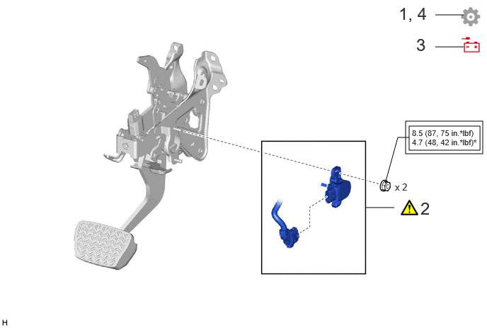
| Procedure | Part Name Code |

|

|

|
|
|---|---|---|---|---|---|
| 1 | INSPECT AND ADJUST BRAKE PEDAL HEIGHT | - | - | - | ( ) |
| 2 | BRAKE PEDAL STROKE SENSOR ASSEMBLY | 89510D | () |
- | - |
| 3 | CONNECT CABLE TO NEGATIVE BATTERY TERMINAL | - | - | - | - |
| 4 | ADJUST BRAKE PEDAL STROKE SENSOR ASSEMBLY | 89510D | - | - | () |

|
Tightening torque for "Major areas involving basic vehicle performance such as moving/turning/stopping": N*m (kgf*cm, ft.*lbf) | - | For use with SST |
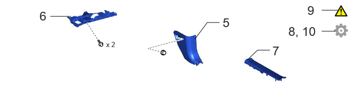
| Procedure | Part Name Code |
|
|
|
|
|---|---|---|---|---|---|
| 5 | COWL SIDE TRIM BOARD RH | 62111C | - | - | - |
| 6 | NO. 1 INSTRUMENT PANEL UNDER COVER SUB-ASSEMBLY | 55606 | - | - | - |
| 7 | FRONT DOOR SCUFF PLATE RH | 67913B | - | - | - |
| 8 | PERFORM CALIBRATION | - | - | - | () |
| 9 | CHECK AND CLEAR DTC | - | - | - | - |
| 10 | INITIALIZATION AFTER RECONNECTING BATTERY TERMINAL | - | - | - | () |
CAUTION / NOTICE / HINT
PROCEDURE

 1.INSPECT AND ADJUST BRAKE PEDAL HEIGHT
89510D 2.INSTALL BRAKE PEDAL STROKE SENSOR ASSEMBLY
When installing a new brake pedal stroke sensor assembly:
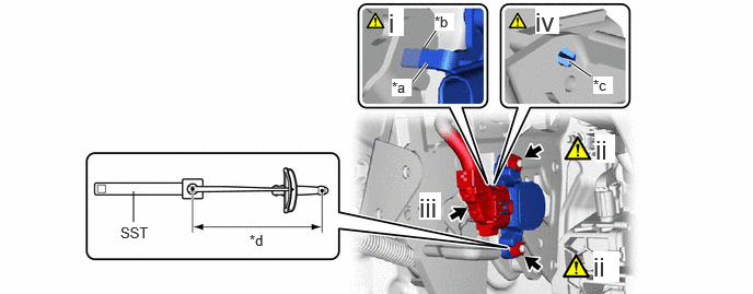
| *a | Brake Pedal Stroke Sensor Assembly Lever | *b | Brake Pedal Groove |
| *c | Brake Pedal Stroke Sensor Assembly Lever Set Pin | *d | Torque Wrench Fulcrum Length |
Engage the brake pedal stroke sensor assembly lever with the brake pedal groove.
- NOTICE:
-
Do not break the brake pedal stroke sensor assembly lever set pin before installing the brake pedal stroke sensor assembly with the 2 nuts.
Using SST, install a new brake pedal stroke sensor assembly to the brake pedal support assembly with the 2 nuts.
- SST
-
09961-00950
- Torque:
- Specified tightening torque : 8.5 N*m (87 kgf*cm, 75 in.*lbf)
- NOTICE:
-
·
Check that there is no foreign matter attached to the contact surface of the brake pedal stroke sensor assembly.
·Check that the tip of the brake pedal stroke sensor assembly lever is protruding from the brake pedal groove.
·Do not drop the brake pedal stroke sensor assembly.
·If the brake pedal stroke sensor assembly has been dropped, replace the brake pedal stroke sensor assembly with a new one.
- HINT:
-
·
Calculate the torque wrench reading when changing the fulcrum length of the torque wrench.
Click hereGeneral>INTRODUCTION>REPAIR INSTRUCTION>PRECAUTION
·When using SST (fulcrum length of 150 mm (5.91 in.)) + torque wrench (fulcrum length of 185 mm (7.28 in.)):
4.7 N*m (48 kgf*cm, 42 in.*lbf)
Connect the connector.
Firmly depress the brake pedal to break the brake pedal stroke sensor assembly lever set pin and remove the broken lever set pin.
- NOTICE:
-
Remove the broken lever set pin.
When reusing the brake pedal stroke sensor assembly:
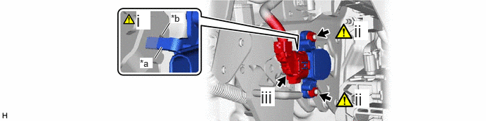
| *a | Brake Pedal Stroke Sensor Assembly Lever | *b | Brake Pedal Groove |
Engage the brake pedal stroke sensor assembly lever with the brake pedal groove.
Install the brake pedal stroke sensor assembly to the brake pedal support assembly and tighten the 2 nuts.
- NOTICE:
-
·
Check that there is no foreign matter attached to the contact surface of the brake pedal stroke sensor assembly.
·Check that the tip of the brake pedal stroke sensor assembly lever is protruding from the brake pedal groove.
·Do not drop the brake pedal stroke sensor assembly.
·If the brake pedal stroke sensor assembly has been dropped, replace the brake pedal stroke sensor assembly with a new one.
- HINT:
-
The nuts will be fully tightened when adjusting the brake pedal stroke sensor assembly.
Connect the connector.
3.CONNECT CABLE TO NEGATIVE BATTERY TERMINAL
89510D 4.ADJUST BRAKE PEDAL STROKE SENSOR ASSEMBLY
|
|
|
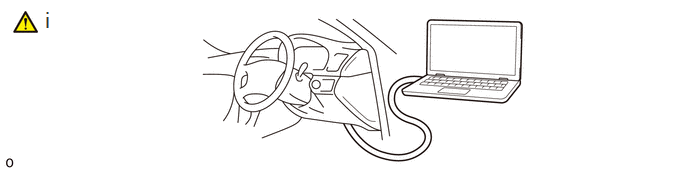
Read the stroke sensor value in the Data List.
- Chassis > Brake Booster > Data List
-
Tester Display Stroke Sensor - 50003 466 207
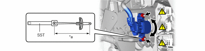
| *a | Torque Wrench Fulcrum Length | - | - |
Turn the brake pedal stroke sensor assembly slowly to the right or left to adjust the output voltage so that it is within the following range.
- Standard Voltage (without the brake pedal depressed):
-
0.8 to 1.2 V
Using SST, tighten the 2 nuts.
- SST
-
09961-00950
- Torque:
- Specified tightening torque : 8.5 N*m (87 kgf*cm, 75 in.*lbf)
- NOTICE:
-
Do not depress the brake pedal after turning the ignition switch to ON.
- HINT:
-
·
Calculate the torque wrench reading when changing the fulcrum length of the torque wrench.
Click hereGeneral>INTRODUCTION>REPAIR INSTRUCTION>PRECAUTION
·When using SST (fulcrum length of 150 mm (5.91 in.)) + torque wrench (fulcrum length of 185 mm (7.28 in.)):
4.7 N*m (48 kgf*cm, 42 in.*lbf)
62111C 5.INSTALL COWL SIDE TRIM BOARD RH
55606 6.INSTALL NO. 1 INSTRUMENT PANEL UNDER COVER SUB-ASSEMBLY
67913B 7.INSTALL FRONT DOOR SCUFF PLATE RH
8.PERFORM CALIBRATION
9. CHECK AND CLEAR DTC
10. INITIALIZATION AFTER RECONNECTING BATTERY TERMINAL
Click hereGeneral>SETUP>WHEN DISCONNECTING OR RECONNECTING BATTERY TERMINAL>WORK PROCEDURE
- HINT:
-
When disconnecting and reconnecting the battery, there is an automatic learning function that completes learning when the respective system is used.
-
Click hereGeneral>SETUP>WHEN DISCONNECTING OR RECONNECTING BATTERY TERMINAL>AUTOMATIC LEARNING CHART