BRAKE SYSTEM (OTHER) BRAKE PEDAL(for RHD) ADJUSTMENT
PROCEDURE

 1.INSPECT AND ADJUST BRAKE PEDAL HEIGHT
- HINT:
-
·
Inspect and adjust the brake pedal height with the floor carpet folded back.
·Perform the inspection from the service hole in the dash panel insulator.
Remove the front door scuff plate RH.
Click hereVehicle Interior>INTERIOR PANELS / TRIM>INSTRUMENT PANEL SAFETY PAD>REMOVAL
- HINT:
-
Use the same procedure described for the LH side.
Remove the No. 1 instrument panel under cover sub-assembly.
Click hereVehicle Interior>INTERIOR PANELS / TRIM>INSTRUMENT PANEL SAFETY PAD>REMOVAL
- HINT:
-
Use the same procedure described for the LHD.
Remove the cowl side trim board RH.
Click hereVehicle Interior>INTERIOR PANELS / TRIM>INSTRUMENT PANEL SAFETY PAD>REMOVAL
- HINT:
-
Use the same procedure described for the LH side.
Check the brake pedal height.
Measure the shortest distance between the brake pedal pad surface and front floor footrest as shown in the illustration.
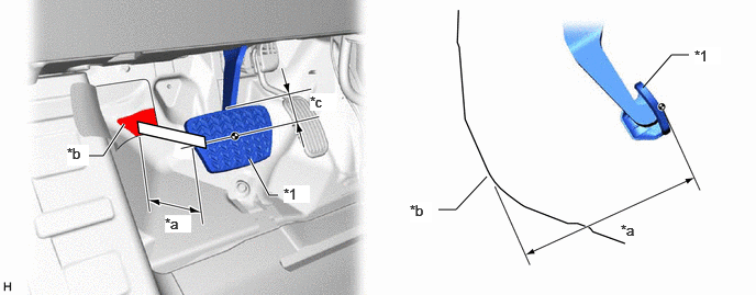
| *1 | Brake Pedal Pad | - | - |
| *a | Brake Pedal Height | *b | Measuring Plane of Front Floor Panel |
| *c | 41 mm (1.61 in.) | - | - |
- Brake Pedal Height from Front Floor Panel:
-
221.2 to 237.2 mm (8.71 to 9.33 in.)
If the brake pedal height is not as specified, inspect and adjust the push rod length according to the procedure below.
Adjust the push rod length.
Remove the lower No. 1 instrument panel airbag assembly.
Click hereVehicle Interior>SUPPLEMENTAL RESTRAINT SYSTEMS>KNEE AIRBAG ASSEMBLY (for Driver Side)>REMOVAL
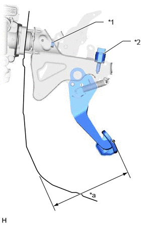
| *1 | Lock Nut |
| *2 | Stop Light Switch Assembly |
| *a | Brake Pedal Height |
Remove the stop light switch assembly.
Click hereVehicle Exterior>LIGHTING (EXT)>STOP LIGHT SWITCH>REMOVAL
Loosen the lock nut and adjust the brake pedal height by turning the push rod to achieve the correct height.
- Brake Pedal Height from Front Floor Panel:
-
221.2 to 237.2 mm (8.71 to 9.33 in.)
Tighten the lock nut.
- Torque:
- 25.5 N*m (260 kgf*cm, 19 ft.*lbf)
Install the stop light switch assembly.
Click hereVehicle Exterior>LIGHTING (EXT)>STOP LIGHT SWITCH>INSTALLATION
Install the lower No. 1 instrument panel airbag assembly.
Click hereVehicle Interior>SUPPLEMENTAL RESTRAINT SYSTEMS>KNEE AIRBAG ASSEMBLY (for Driver Side)>INSTALLATION
Install the cowl side trim board RH.
Click hereVehicle Interior>INTERIOR PANELS / TRIM>INSTRUMENT PANEL SAFETY PAD>INSTALLATION
- HINT:
-
Use the same procedure described for the LH side.
Install the No. 1 instrument panel under cover sub-assembly.
Click hereVehicle Interior>INTERIOR PANELS / TRIM>INSTRUMENT PANEL SAFETY PAD>INSTALLATION
- HINT:
-
Use the same procedure described for the LHD.
Install the front door scuff plate RH.
Click hereVehicle Interior>INTERIOR PANELS / TRIM>INSTRUMENT PANEL SAFETY PAD>INSTALLATION
- HINT:
-
Use the same procedure described for the LH side.
89510D 2.INSPECT AND ADJUST BRAKE PEDAL STROKE SENSOR ASSEMBLY
- NOTICE:
-
Do not depress the brake pedal after turning the ignition switch to ON.
Inspect the brake pedal stroke sensor assembly.
Read the stroke sensor value without the brake pedal depressed.
- Chassis > Brake Booster > Data List
-
Tester Display Stroke Sensor - 50003 466 207
- Standard Voltage (without the brake pedal depressed):
-
0.8 to 1.2 V
- HINT:
-
If the stroke sensor value is not within the standard voltage, adjust the brake pedal stroke sensor assembly.
Adjust the brake pedal stroke sensor assembly.
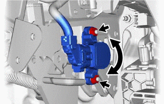
Loosen the 2 nuts.
Remove the No. 1 instrument panel under cover sub-assembly.
Click hereVehicle Interior>INTERIOR PANELS / TRIM>INSTRUMENT PANEL SAFETY PAD>REMOVAL
Read the stroke sensor value in the Data List, and turn the brake pedal stroke sensor assembly slowly to the right or left to adjust the output voltage so that it is within the following range.
- Standard Voltage (without the brake pedal depressed):
-
0.8 to 1.2 V
Using a union nut wrench, tighten the 2 nuts.
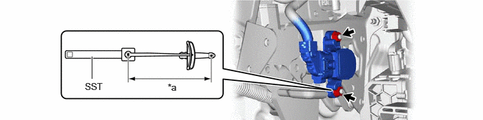
| *a | Torque Wrench Fulcrum Length | - | - |
- Torque:
- Specified tightening torque : 8.5 N*m (87 kgf*cm, 75 in.*lbf)
- SST
-
09961-00950
- NOTICE:
-
Do not depress the brake pedal after turning the ignition switch to ON.
- HINT:
-
·
Calculate the torque wrench reading when changing the fulcrum length of the torque wrench.
Click hereGeneral>INTRODUCTION>REPAIR INSTRUCTION>PRECAUTION
·When using SST (fulcrum length of 150 mm (5.91 in.)) + torque wrench (fulcrum length of 185 mm (7.28 in.)):
4.7 N*m (48 kgf*cm, 42 in.*lbf)
Install the No. 1 instrument panel under cover sub-assembly.
Click hereVehicle Interior>INTERIOR PANELS / TRIM>INSTRUMENT PANEL SAFETY PAD>INSTALLATION
Perform calibration.
Click hereBrake>BRAKE CONTROL / DYNAMIC CONTROL SYSTEMS>ELECTRONICALLY CONTROLLED BRAKE SYSTEM>UTILITY
3.PERFORM CALIBRATION
4.INSPECT BRAKE PEDAL FREE PLAY
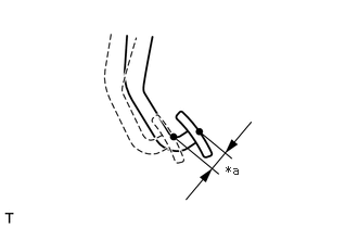
| *a | Brake Pedal Free Play |
Depress the brake pedal until a slight resistance is felt. Measure the distance as shown in the illustration.
- Brake Pedal Free Play:
-
1.0 to 6.0 mm (0.0394 to 0.236 in.)
If the brake pedal free play is not as specified, check the stop light switch clearance.
Click hereVehicle Exterior>LIGHTING (EXT)>STOP LIGHT SWITCH>INSTALLATION
If the brake pedal free play is as specified, proceed to the Inspect Brake Pedal Reserve Distance procedure.
5.INSPECT BRAKE PEDAL RESERVE DISTANCE
- HINT:
-
·
Inspect and adjust the brake pedal height with the floor carpet folded back.
·Perform the inspection from the service hole in the dash panel insulator.
With the engine running, depress the brake pedal and measure the brake pedal reserve distance as shown in the illustration.
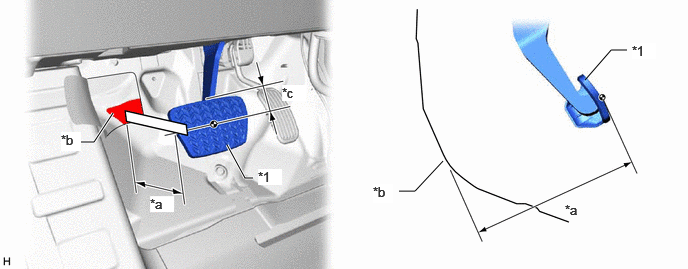
| *1 | Brake Pedal Pad | - | - |
| *a | Brake Pedal Height | *b | Measuring Plane of Front Floor Panel |
| *c | 41 mm (1.61 in.) | - | - |
- Brake Pedal Reserve Distance from Front Floor Panel at 300 N (31 kgf, 67.4 lbf):
-
145 mm (5.71 in.) or more