Home › Drivetrain › AJA0F (AUTOMATIC TRANSMISSION / TRANSAXLE) › VALVE BODY ASSEMBLY › 2021.04–2021.07
RM38G0E _52 Drivetrain _100435 AJA0F AUTOMATIC TRANSMISSION / TRANSAXLE _0467303 VALVE BODY ASSEMBLY A

AJA0F AUTOMATIC TRANSMISSION / TRANSAXLE  VALVE BODY ASSEMBLY  REMOVAL  


CAUTION / NOTICE / HINT
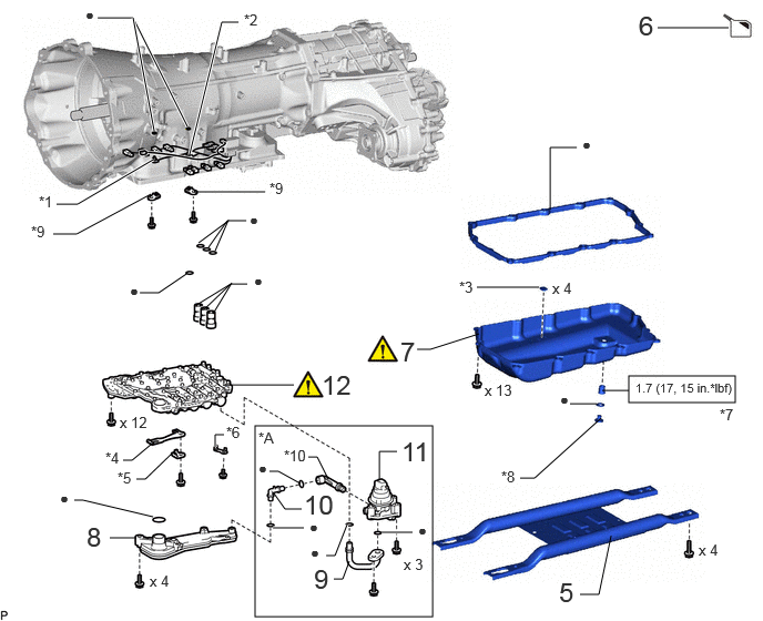
COMPONENTS (REMOVAL)
C459129N01
5.729,1.375 7.125,2.74 1.396,1.365 4.406,0.781 4.406,0.365 false 6.302,2.344 6.302,1.927 false 0.5,2.417 0.75,1.167 0.75,1.167 1,1.167 false 1.844,3.333 1.979,3.531 1.979,3.531 2.229,3.531 false 3.167,2.333 2.833,2.333 false 4.833,1.417 5.25,1 5.25,1 5.5,1 false 1.885,2.448 2.344,2.646 0.458,0.198 10 false x 5 1.625,3.5 2.083,3.698 0.458,0.198 10 false x 2 0.625,2.917 1.083,3.115 0.458,0.198 10 false x 2 4.74,2.031 5.323,2.229 0.583,0.198 10 false x 6 (*A) 4.365,0.823 4.76,1.188 0.396,0.365 18 false 3 6.24,2.396 6.635,2.76 0.396,0.365 18 false 4 1.021,1.052 1.25,1.333 0.229,0.281 10 false *2 2.271,3.427 2.469,3.688 0.198,0.26 10 false *1 3.198,2.177 3.594,2.542 0.396,0.365 18 false 1 5.531,0.833 5.927,1.198 0.396,0.365 18 false 2 5.792,1.417 6.104,1.615 0.313,0.198 10 false *A 4.75,2.229 5.333,2.427 0.583,0.198 10 false x 4 (*B)

Procedure Part Name Code
Z101186

Z101188

Z101187

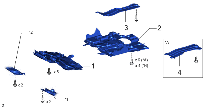
1 NO. 1 ENGINE UNDER COVER ASSEMBLY 51410 - - -
2 NO. 2 ENGINE UNDER COVER ASSEMBLY 51420 - - -
3 FRAME UNDER COVER ASSEMBLY RH 51430A - - -
4 FRAME UNDER COVER ASSEMBLY LH 51450C - - -

*A w/ Cover *B w/o Cover
*1 ENGINE SIDE COVER SUB-ASSEMBLY LH *2 ENGINE SIDE COVER SUB-ASSEMBLY RH

C456941N01
5.906,3.531 6.906,3.781 1,0.25 2.396,4 4.063,5.792 1.667,1.792 1.156,4.323 1.24,4.323 1.24,4.323 1.427,4.167 false 1.844,2.865 2.167,2.667 2.167,2.667 2.323,2.667 false 1.958,2.323 2.135,2.073 false 2,2.948 2.177,2.656 false 1.865,2.281 2.146,2.073 2.146,2.073 2.313,2.073 false 2.021,2.354 2.146,2.063 false 1.917,2.906 2.167,2.667 false 1.313,2.75 1.49,2.75 1.49,2.75 1.75,2.573 false 2.094,3.615 2.76,3.615 false 1.031,5.052 1.281,5.052 false 2.021,4.198 2.021,4.083 2.021,4.083 2.104,4.083 true 1.823,1.802 2.49,1.802 false 0.5,2.198 0.719,2.198 0.719,2.198 1.417,1.823 false 0.917,0.167 1.25,0.167 1.25,0.167 1.76,1.188 true 1.25,0.167 1.448,1.229 true 1.781,1.448 2.083,0.208 2.083,0.208 2.24,0.208 true 0.531,1.917 0.729,1.917 0.729,1.917 1.438,1.5 true 6.177,0.26 6.844,0.26 false 5.448,5.583 5.625,5.583 5.625,5.583 5.74,5.031 false 5.354,3.792 5.604,3.792 false 5.656,3.667 5.906,3.667 false 4.885,4.49 5.021,4.49 5.021,4.49 5.646,3.927 false 3.917,3.281 4.042,3.281 4.042,3.281 4.5,3.135 false 4.479,2.698 5.063,2.698 false 5.167,1.969 5.167,1.385 5.167,1.385 5.417,1.385 false 1.281,4.5 1.365,4.5 1.365,4.5 1.656,4.219 false 0.698,4.698 0.781,4.698 0.781,4.698 1.438,4.854 false 3.563,4.5 3.563,4.24 3.563,4.24 3.729,4.24 false 3.063,5.219 3.146,5.219 3.146,5.219 3.26,4.927 true 3.583,5 3.875,5 true 3.135,5.438 3.219,5.438 3.219,5.438 3.281,5.271 false 2.563,4.958 2.854,4.958 true 2.573,4.635 2.677,4.781 2.677,4.781 2.833,4.781 false 2.531,4.427 2.615,4.427 2.615,4.427 2.823,4.542 false 2.896,4.292 2.979,4.292 2.979,4.292 3.083,4.5 false 1.125,3.885 1.74,4.083 0.615,0.198 10 false x 12 0.99,4.219 1.302,4.417 0.313,0.198 10 false *4 2.385,2.552 2.813,2.833 0.427,0.281 10 false ● 2.344,1.979 2.5,2.177 0.156,0.198 10 false ● 1.219,2.646 1.5,2.948 0.281,0.302 10 false ● 6,0.094 6.281,0.448 0.281,0.354 18 false 6 0.813,4.896 1.094,5.25 0.281,0.354 18 false 8 0.563,4.594 0.844,4.896 0.281,0.302 10 false ● 2.125,3.979 2.438,4.177 0.313,0.198 10 false *6 2.531,1.688 2.844,1.885 0.313,0.198 10 false *9 0.802,0.052 1.083,0.354 0.281,0.302 10 false ● 2.292,0.104 2.604,0.302 0.313,0.198 10 false *2 0.365,1.813 0.677,2.01 0.313,0.198 10 false *1 5.25,5.417 5.531,5.771 0.281,0.354 18 false 5 3.021,3.469 3.417,3.833 0.396,0.365 18 false 12 6.563,5.083 7.104,5.323 0.542,0.24 10 false x 4 5.26,3.667 5.469,3.865 0.208,0.198 10 false ● 4.313,2.615 4.625,2.813 0.313,0.198 10 false *3 5.188,2.625 5.802,2.823 0.615,0.198 10 false x 4 6.76,3.813 7.073,4.01 0.313,0.198 10 false *7 4.708,4.396 5.021,4.594 0.313,0.198 10 false *8 4.552,3.583 5.167,3.781 0.615,0.198 10 false x 13 3.76,3.156 4.042,3.51 0.281,0.354 18 false 7 1.406,5.375 1.958,5.615 0.552,0.24 10 false x 4 0.292,2.094 0.604,2.292 0.313,0.198 10 false *9 5.469,1.271 5.781,1.469 0.313,0.198 10 false ● 5.969,3.573 7.031,3.75 1.063,0.177 8 false 1.7 (17, 15 in.*lbf) 3.792,5.219 4.104,5.417 0.313,0.198 10 false x 3 1.104,4.406 1.417,4.604 0.313,0.198 10 false *5 3.771,4.094 4.115,4.458 0.344,0.365 18 false 11 2.854,4.594 3.25,4.875 0.396,0.281 18 false 10 2.427,4.031 2.74,4.229 0.313,0.198 10 false *A 2.917,5.104 3.198,5.406 0.281,0.302 10 false ● 3.927,4.896 4.208,5.198 0.281,0.302 10 false ● 2.948,5.292 3.344,5.573 0.396,0.281 18 false 9 2.906,4.865 3.188,5.167 0.281,0.302 10 false ● 2.427,4.313 2.708,4.615 0.281,0.302 10 false ● 2.667,4.198 2.979,4.396 0.313,0.198 10 false *10

Procedure Part Name Code
Z101186

Z101188

Z101187

5 OIL PAN PROTECTOR ASSEMBLY 51440 - - -
6 DRAIN AUTOMATIC TRANSMISSION FLUID - - (Click here) -
7 AUTOMATIC TRANSMISSION OIL PAN SUB-ASSEMBLY 35106 (Click here) - -
8 VALVE BODY OIL STRAINER ASSEMBLY 35330 - - -
9 NO. 2 TRANSMISSION OIL PIPE 33129G - - -
10 NO. 3 TRANSMISSION OIL PIPE 33129H - - -
11 OIL PUMP WITH MOTOR ASSEMBLY 35300D - - -
12 TRANSMISSION VALVE BODY ASSEMBLY 35400A (Click here) - -

*A w/ Stop and Start System - -
*1 NO. 1 ATF TEMPERATURE SENSOR *2 NO. 2 ATF TEMPERATURE SENSOR
*3 TRANSMISSION OIL CLEANER MAGNET *4 MANUAL DETENT SPRING SUB-ASSEMBLY
*5 MANUAL DETENT SPRING COVER *6 WIRE HARNESS CLAMP
*7 NO. 1 TRANSMISSION OIL FILLER TUBE *8 OVERFLOW PLUG
*9 LOCK PLATE *10 NO. 4 TRANSMISSION OIL PIPE
V100146

N*m (kgf*cm, ft.*lbf): Specified torque ● Non-reusable part

The necessary procedures (adjustment, calibration, initialization, or registration) that must be performed after parts are removed, installed, or replaced during the transmission valve body assembly removal/installation are shown below.

Necessary Procedures After Parts Removed/Installed/Replaced
Replaced Part or Performed Procedures Necessary Procedures Effect/Inoperative Function when Necessary Procedures are not Performed Link
Transmission valve body assembly Perform road test to allow TCM to learn
·

Large shift shock

·

Engine overruns


(Click here)
Automatic transmission fluid ATF thermal degradation estimate reset The value of the Data List item "ATF Thermal Degradation Estimate" is not estimated correctly. (Click here)

PROCEDURE

Hide 51410 1.REMOVE NO. 1 ENGINE UNDER COVER ASSEMBLY

Hide 51420 2.REMOVE NO. 2 ENGINE UNDER COVER ASSEMBLY

Hide 51430A 3.REMOVE FRAME UNDER COVER ASSEMBLY RH

Hide 51450C 4.REMOVE FRAME UNDER COVER ASSEMBLY LH (w/ Cover)

Hide 51440 5.REMOVE OIL PAN PROTECTOR ASSEMBLY

a.
C456927


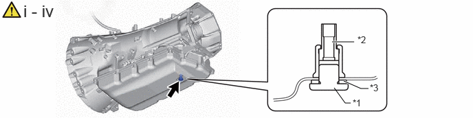
Hide 6.DRAIN AUTOMATIC TRANSMISSION FLUID

a.
C456936C01
5.063,1.333 5.229,1.563 5.229,1.563 5.313,1.563 false 5.031,0.635 5.365,0.635 true 5.208,1.229 5.469,1.344 5.469,1.344 5.583,1.344 true 5.344,1.479 5.656,1.635 0.313,0.156 10 false *1 5.417,0.521 5.729,0.677 0.313,0.156 10 false *2 5.604,1.25 5.917,1.406 0.313,0.156 10 false *3 0.354,0.021 1.229,0.292 0.875,0.271 18 false i - iv
*1 Overflow Plug *2 No. 1 Transmission Oil Filler Tube
*3 Gasket - -


i.

Using a 6 mm hexagon socket wrench, remove the overflow plug and gasket from the automatic transmission assembly and drain the automatic transmission fluid.


ii.

Using a 6 mm hexagon socket wrench, remove the No. 1 transmission oil filler tube from the automatic transmission assembly and drain the automatic transmission fluid.


iii.

Using a 6 mm hexagon socket wrench, install the No. 1 transmission oil filler tube to the automatic transmission assembly.

Torque:
1.7 N*m (17 kgf*cm, 15 in.*lbf)


iv.

Temporarily install the gasket and overflow plug to the automatic transmission assembly.

HINT:

Gasket replacement and tightening of the overflow plug are performed after the automatic transmission fluid level is adjusted.


Hide 35106 7.REMOVE AUTOMATIC TRANSMISSION OIL PAN SUB-ASSEMBLY
a.
C456937N01
0.573,0.229 0.854,0.583 0.281,0.354 18 false i 4.083,0.271 4.365,0.625 0.281,0.354 18 false ii 2.49,1.948 2.771,2.302 0.281,0.354 18 false iii

i.

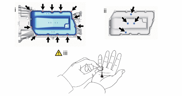
Remove the 13 bolts, automatic transmission oil pan sub-assembly and automatic transmission oil pan gasket from the automatic transmission case sub-assembly.


ii.

Remove the 4 transmission oil cleaner magnets from the automatic transmission oil pan sub-assembly.


iii.

Examine the particles in the automatic transmission oil pan sub-assembly.

1.

Use the removed transmission oil cleaner magnets to collect any steel chips.

Examine the chips and particles in the automatic transmission oil pan sub-assembly and on the transmission oil cleaner magnets to determine what type of wear might be found in the automatic transmission assembly.

Result:
Steel (magnetic):

Bearing, gear and clutch plate wear

Brass (non-magnetic):

Bushing wear


Hide 35330 8.REMOVE VALVE BODY OIL STRAINER ASSEMBLY
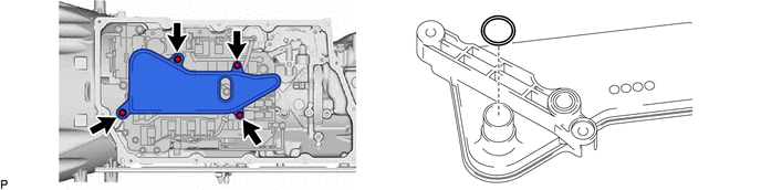
a.
C455589


Hide 33129G 9.REMOVE NO. 2 TRANSMISSION OIL PIPE (w/ Stop And Start System)

Hide 33129H 10.REMOVE NO. 3 TRANSMISSION OIL PIPE (w/ Stop And Start System)

Hide 35300D 11.REMOVE OIL PUMP WITH MOTOR ASSEMBLY (w/ Stop And Start System)

a.
C456964


Hide 35400A 12.REMOVE TRANSMISSION VALVE BODY ASSEMBLY
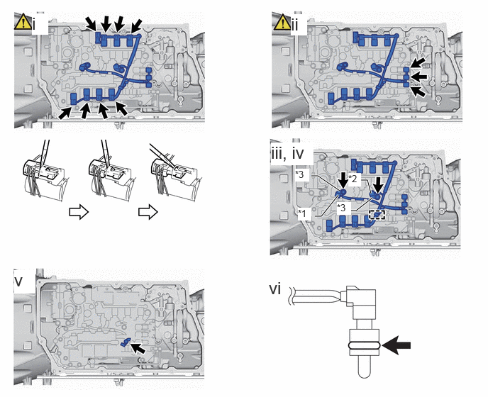
a.
C459138C01
4.573,2.583 4.667,2.583 4.667,2.583 4.99,2.802 true 4.625,3.177 4.719,3.177 4.719,3.177 4.969,2.865 true 5.135,3.094 5.229,3.094 5.229,3.094 5.469,2.906 true 5.302,2.646 5.396,2.646 5.396,2.646 5.448,2.844 true 0.469,0.198 0.708,0.51 0.24,0.313 18 true i 4.271,0.208 4.51,0.521 0.24,0.313 18 true ii 3.979,2.094 4.604,2.427 0.625,0.333 18 true iii, iv 0.208,3.969 0.521,4.313 0.313,0.344 18 true v 3.948,4.083 4.365,4.49 0.417,0.406 18 false vi 4.375,3.052 4.573,3.24 0.198,0.188 10 true *1 5.115,2.542 5.302,2.74 0.188,0.198 10 true *2 4.333,2.479 4.542,2.667 0.208,0.188 10 true *3 4.948,2.969 5.156,3.156 0.208,0.188 10 true *3
*1 No. 1 ATF Temperature Sensor *2 No. 2 ATF Temperature Sensor
*3 Lock Plate - -


i.

Using a screwdriver, disconnect the 8 solenoid valve connectors of each of the solenoid valves as shown in the illustration.

NOTICE:

Do not damage the solenoid valves or solenoid valve connectors.


ii.

Disconnect the 3 solenoid valve connectors.

NOTICE:

Do not damage the solenoid valves or solenoid valve connectors.


iii.

Remove the 2 bolts and 2 lock plates, and disconnect the No. 1 ATF temperature sensor and No. 2 ATF temperature sensor from the transmission valve body assembly.


iv.

Disconnect the transmission wire from the wire harness clamp.


v.

Remove the bolt and wire harness clamp.


vi.

Remove the 2 O-rings from the No. 1 ATF temperature sensor and No. 2 ATF temperature sensor.
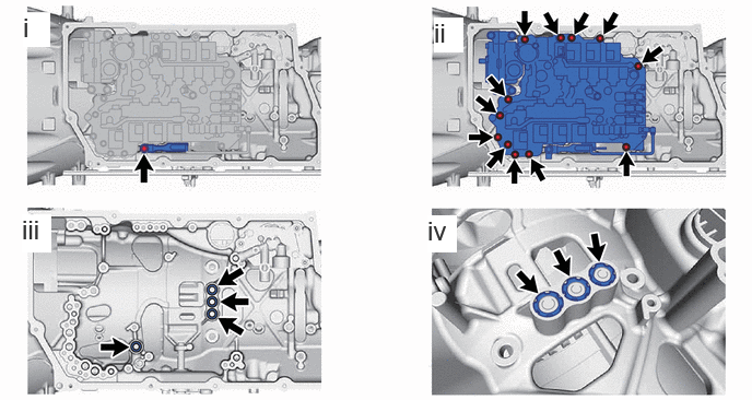


b.
C459123N01
0.219,0.115 0.479,0.448 0.26,0.333 18 true i 0.208,2.042 0.49,2.406 0.281,0.365 18 true iii 4.135,0.167 4.417,0.5 0.281,0.333 18 true ii 4.073,2.052 4.354,2.406 0.281,0.354 18 true iv

i.

Remove the bolt, manual detent spring cover and manual detent spring sub-assembly from the automatic transmission case sub-assembly.


ii.

Remove the 12 bolts and transmission valve body assembly from the automatic transmission case sub-assembly.


iii.

Remove the 4 gaskets from the automatic transmission case sub-assembly.


iv.

Remove the 3 brake drum gaskets from the automatic transmission case sub-assembly.