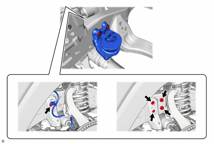
V35A-FTS ENGINE MECHANICAL ENGINE ASSEMBLY REMOVAL
CAUTION / NOTICE / HINT
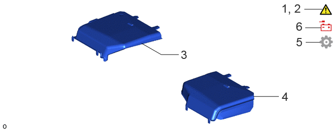
| Procedure | Part Name Code |

|

|

|
|
|---|---|---|---|---|---|
| 1 | PRECAUTION | - | ( ) |
- | - |
| 2 | DISCHARGE FUEL SYSTEM PRESSURE | - | () |
- | - |
| 3 | ENGINE SIDE COVER RH | 51473C | - | - | - |
| 4 | ENGINE SIDE COVER LH | 51474B | - | - | - |
| 5 | RELEASE PARKING BRAKE | - | - | - | () |
| 6 | DISCONNECT CABLE FROM NEGATIVE BATTERY TERMINAL | - | - | - | - |
| Procedure | Part Name Code |
|
|
|
|
|---|---|---|---|---|---|
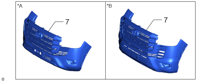
| 7 | FRONT BUMPER ASSEMBLY | - | - | - | - |
| *A | for Standard | *B | for Aero Type |
| Procedure | Part Name Code |
|
|
|
|
|---|---|---|---|---|---|
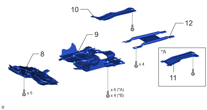
| 8 | NO. 1 ENGINE UNDER COVER ASSEMBLY | 51410 | - | - | - |
| 9 | NO. 2 ENGINE UNDER COVER ASSEMBLY | 51420 | - | - | - |
| 10 | FRAME UNDER COVER ASSEMBLY RH | 51430A | - | - | - |
| 11 | FRAME UNDER COVER ASSEMBLY LH (w/ Cover) | 51450C | - | - | - |
| 12 | OIL PAN PROTECTOR ASSEMBLY | 51440 | - | - | - |
| *A | w/ Cover | *B | w/o Cover |
| Procedure | Part Name Code |
|
|
|
|
|---|---|---|---|---|---|
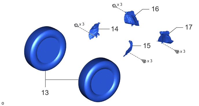
| 13 | FRONT WHEEL | - | - | - | - |
| 14 | FRONT FENDER APRON TRIM PACKING A | 53782 | - | - | - |
| 15 | FRONT FENDER APRON TRIM PACKING B | 53783 | - | - | - |
| 16 | FRONT FENDER APRON TRIM PACKING C | 53784 | - | - | - |
| 17 | FRONT FENDER APRON TRIM PACKING D | 53785B | - | - | - |
| Procedure | Part Name Code |
|
|
|
|
|---|---|---|---|---|---|
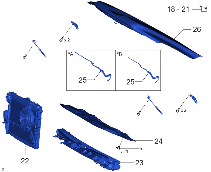
| 18 | DRAIN ENGINE OIL | - | - | () |
- |
| 19 | DRAIN ENGINE COOLANT | - | - | () |
- |
| 20 | DRAIN COOLANT (for Intercooler) | - | - | () |
- |
| 21 | DRAIN AUTOMATIC TRANSMISSION FLUID | - | - | () |
- |
| 22 | RADIATOR ASSEMBLY | 16400 | - | - | - |
| 23 | COWL TOP VENTILATOR LOUVER SUB-ASSEMBLY | 55708 | - | - | - |
| 24 | HOOD INSULATOR | 53341B | - | - | - |
| 25 | WINDSHIELD WASHER HOSE ASSEMBLY | 85370 | - | - | - |
| 26 | HOOD SUB-ASSEMBLY | 53301 | - | - | - |
| *A | w/ Heater | *B | w/o Heater |
| ● | Non-reusable part | - | - |
| Procedure | Part Name Code |
|
|
|
|
|---|---|---|---|---|---|
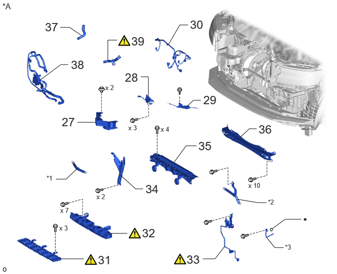
| 27 | HOOD LOCK RELEASE LEVER PROTECTOR | 53525 | - | - | - |
| 28 | HOOD LOCK ASSEMBLY | 53510 | - | - | - |
| 29 | HOOD LOCK CONTROL CABLE COVER | 53629 | - | - | - |
| 30 | ENGINE ROOM MAIN WIRE | 82111 | - | - | - |
| 31 | FRONT BUMPER ENERGY ABSORBER | 52611 | () |
- | - |
| 32 | FRONT BUMPER CENTER UPPER RETAINER | 52521 | () |
- | - |
| 33 | AIR CONDITIONING TUBE AND ACCESSORY ASSEMBLY AND NO. 2 AIR CONDITIONING TUBE AND ACCESSORY ASSEMBLY | 88710E | () |
- | - |
| 34 | HOOD LOCK SUPPORT BRACE SUB-ASSEMBLY | 53209B | - | - | - |
| 35 | UPPER RADIATOR SUPPORT SUB-ASSEMBLY | 53205 | - | - | - |
| 36 | FRONT CROSS MEMBER | 57161C | - | - | - |
| 37 | NO. 4 WATER BY-PASS HOSE | 16267C | - | - | - |
| 38 | OIL COOLER TUBE AND OIL COOLER HOSE WITH OIL COOLER ASSEMBLY | - | - | - | - |
| 39 | NO. 4 WATER BY-PASS HOSE ASSEMBLY | 162A0 | () |
- | - |
| *A | for LHD | - | - |
| *1 | NO. 9 WATER BY-PASS HOSE | *2 | NO. 2 WATER BY-PASS HOSE ASSEMBLY |
| *3 | COOLER REFRIGERANT LIQUID PIPE A | - | - |
| ● | Non-reusable part | - | - |
| Procedure | Part Name Code |
|
|
|
|
|---|---|---|---|---|---|
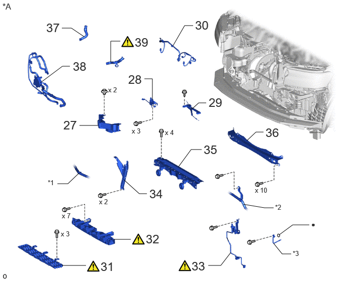
| 27 | HOOD LOCK RELEASE LEVER PROTECTOR | 53525 | - | - | - |
| 28 | HOOD LOCK ASSEMBLY | 53510 | - | - | - |
| 29 | HOOD LOCK CONTROL CABLE COVER | 53629 | - | - | - |
| 30 | ENGINE ROOM MAIN WIRE | 82111 | - | - | - |
| 31 | FRONT BUMPER ENERGY ABSORBER | 52611 | () |
- | - |
| 32 | FRONT BUMPER CENTER UPPER RETAINER | 52521 | () |
- | - |
| 33 | AIR CONDITIONING TUBE AND ACCESSORY ASSEMBLY AND NO. 2 AIR CONDITIONING TUBE AND ACCESSORY ASSEMBLY | 88710E | () |
- | - |
| 34 | HOOD LOCK SUPPORT BRACE SUB-ASSEMBLY | 53209B | - | - | - |
| 35 | UPPER RADIATOR SUPPORT SUB-ASSEMBLY | 53205 | - | - | - |
| 36 | FRONT CROSS MEMBER | 57161C | - | - | - |
| 37 | NO. 4 WATER BY-PASS HOSE | 16267C | - | - | |
| 38 | OIL COOLER TUBE AND OIL COOLER HOSE WITH OIL COOLER ASSEMBLY | - | - | - | - |
| 39 | NO. 4 WATER BY-PASS HOSE ASSEMBLY | 162A0 | () |
- | - |
| *A | for RHD | - | - |
| *1 | NO. 9 WATER BY-PASS HOSE | *2 | NO. 2 WATER BY-PASS HOSE ASSEMBLY |
| *3 | COOLER REFRIGERANT LIQUID PIPE A | - | - |
| ● | Non-reusable part | - | - |
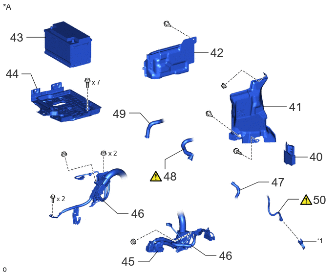
| Procedure | Part Name Code |
|
|
|
|
|---|---|---|---|---|---|
| 40 | UPPER ENGINE SIDE UNDER COVER PLATE LH | 51478C | - | - | - |
| 41 | REAR ENGINE SIDE UNDER COVER ASSEMBLY LH | 51470C | - | - | - |
| 42 | ENGINE SIDE UNDER COVER RH | 51448M | - | - | - |
| 43 | BATTERY | 28800 | - | - | - |
| 44 | BATTERY CARRIER ASSEMBLY | 74410 | - | - | - |
| 45 | ECM CONNECTOR | - | - | - | - |
| 46 | ENGINE WIRE | 82121 | - | - | - |
| 47 | NO. 1 FUEL VAPOR FEED HOSE | 23826 | - | - | - |
| 48 | WATER HOSE SUB-ASSEMBLY | 87209 | () |
- | - |
| 49 | HEATER WATER HOSE OUTLET A | - | - | - | - |
| 50 | FUEL TUBE SUB-ASSEMBLY | 23901 | () |
- | - |
| *A | for LHD | - | - |
| *1 | FUEL PIPE CLAMP | - | - |
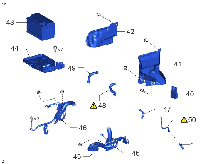
| Procedure | Part Name Code |
|
|
|
|
|---|---|---|---|---|---|
| 40 | UPPER ENGINE SIDE UNDER COVER PLATE LH | 51478C | - | - | - |
| 41 | REAR ENGINE SIDE UNDER COVER ASSEMBLY LH | 51470C | - | - | - |
| 42 | ENGINE SIDE UNDER COVER RH | 51448M | - | - | - |
| 43 | BATTERY | 28800 | - | - | - |
| 44 | BATTERY CARRIER ASSEMBLY | 74410 | - | - | - |
| 45 | ECM CONNECTOR | - | - | - | - |
| 46 | ENGINE WIRE | 82121 | - | - | - |
| 47 | NO. 1 FUEL VAPOR FEED HOSE | 23826 | - | - | - |
| 48 | WATER HOSE SUB-ASSEMBLY | 87209 | () |
- | - |
| 49 | HEATER WATER HOSE OUTLET A | - | - | - | - |
| 50 | FUEL TUBE SUB-ASSEMBLY | 23901 | () |
- | - |
| *A | for RHD | - | - |
| *1 | FUEL PIPE CLAMP | - | - |
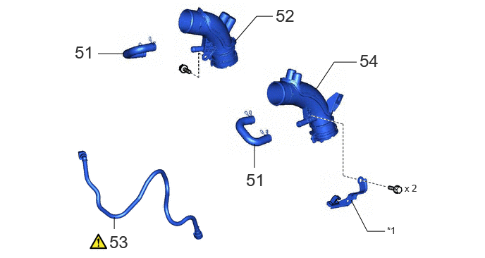
| Procedure | Part Name Code |
|
|
|
|
|---|---|---|---|---|---|
| 51 | NO. 2 PCV HOSE (NO. 2 VENTILATION HOSE) | 12262 | - | - | - |
| 52 | NO. 1 AIR INLET DUCT | 17311 | - | - | - |
| 53 | FUEL TUBE SUB-ASSEMBLY | 23901 | () |
- | - |
| 54 | NO. 2 AIR INLET DUCT | 17312D | - | - | - |
| *1 | COOL AIR INLET BRACKET | - | - |
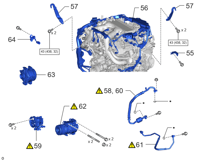
| Procedure | Part Name Code |
|
|
|
|
|---|---|---|---|---|---|
| 55 | NO. 6 TURBO INSULATOR | 1728C | - | - | - |
| 56 | ENGINE WIRE | 82121 | - | - | - |
| 57 | ENGINE HANGER | - | - | - | - |
| 58 | DISCONNECT SUCTION HOSE SUB-ASSEMBLY | 88704 | () |
- | - |
| 59 | VANE PUMP ASSEMBLY | 44310 | () |
- | - |
| 60 | REMOVE SUCTION HOSE SUB-ASSEMBLY | 88704 | () |
- | - |
| 61 | NO. 1 COOLER REFRIGERANT DISCHARGE HOSE | 88711 | () |
- | - |
| 62 | COMPRESSOR ASSEMBLY WITH MAGNET CLUTCH | - | () |
- | - |
| 63 | GENERATOR ASSEMBLY | 27020 | - | - | - |
| 64 | NO. 10 ENGINE WIRE | 8212B | - | - | - |

|
N*m (kgf*cm, ft.*lbf): Specified torque | ● | Non-reusable part |
| Procedure | Part Name Code |
|
|
|
|
|---|---|---|---|---|---|
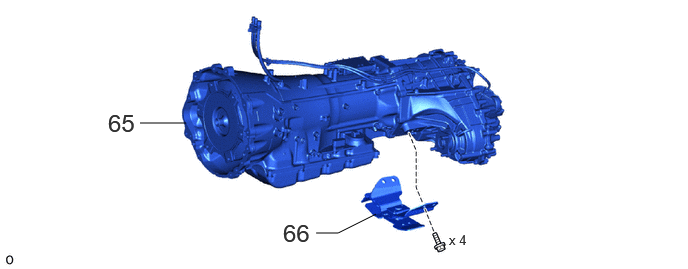
| 65 | AUTOMATIC TRANSMISSION ASSEMBLY WITH TRANSFER ASSEMBLY | - | - | - | - |
| 66 | REAR ENGINE MOUNTING INSULATOR | 12371A | - | - | - |
| Procedure | Part Name Code |
|
|
|
|
|---|---|---|---|---|---|
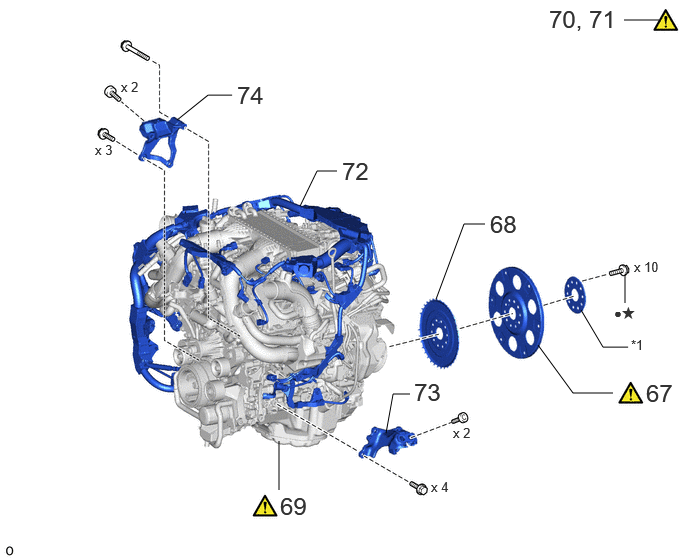
| 67 | DRIVE PLATE AND RING GEAR SUB-ASSEMBLY | 32101 | () |
- | - |
| 68 | NO. 1 CRANKSHAFT POSITION SENSOR PLATE | 19315 | - | - | - |
| 69 | ENGINE ASSEMBLY | - | () |
- | - |
| 70 | INSTALL ENGINE STAND | - | () |
- | - |
| 71 | ENGINE HANGER | - | () |
- | - |
| 72 | ENGINE WIRE | 82121 | - | - | - |
| 73 | FRONT NO. 1 ENGINE MOUNTING BRACKET LH | 12315 | - | - | - |
| 74 | FRONT NO. 1 ENGINE MOUNTING BRACKET RH | 12311 | - | - | - |
| *1 | REAR DRIVE PLATE SPACER | - | - |
| ● | Non-reusable part | ★ | Precoated part |
| Procedure | Part Name Code |
|
|
|
|
|---|---|---|---|---|---|
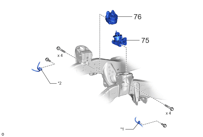
| 75 | FRONT ENGINE MOUNTING INSULATOR LH | 12362A | - | - | - |
| 76 | FRONT ENGINE MOUNTING INSULATOR RH | 12361E | - | - | - |
| *1 | FRONT NO. 2 FLEXIBLE HOSE BRACKET RH | *2 | FRONT NO. 2 FLEXIBLE HOSE BRACKET LH |
CAUTION / NOTICE / HINT
The necessary procedures (adjustment, calibration, initialization, or registration) that must be performed after parts are removed, installed, or replaced during the engine assembly removal/installation are shown below.
| Replaced Part or Performed Procedure | Necessary Procedure | Effect/Inoperative Function when Necessary Procedure not Performed | Link |
|---|---|---|---|
| Battery terminal is disconnected/reconnected | Memorize steering angle neutral point | Parking assist monitor system | () |
| Multi-terrain monitor system | () |
||
| Panoramic view monitor system | () |
||
|
·
Engine assembly
·
Air leaks from intake system
·
Gas leaks from exhaust system |
Inspection after repair |
·
Poor idle, etc.
·
Engine start function, etc. |
() |
| Engine assembly | Perform road test to allow TCM to learn |
·
Large shift shock
·
Engine overruns |
() |
| Automatic transmission assembly | ECU configuration | - | () |
| Update ECU security key | Vehicle control history (RoB) are stored | () |
|
| Automatic transmission fluid | ATF thermal degradation estimate reset | The value of the Data List item "ATF Thermal Degradation Estimate" is not estimated correctly. | () |
| Front bumper assembly (Including removal and installation) | Front television camera view adjustment | Panoramic view monitor system | () |
- HINT:
-
When the cable is disconnected/reconnected to the battery terminal, systems temporarily stop operating. However, each system has a function that completes learning the first time the system is used.
-
·
Learning completes when vehicle is driven
Effect/Inoperative Function When Necessary Procedures are not Performed Necessary Procedures Link Stop and start system Drive the vehicle until stop and start control is permitted (approximately 5 to 60 minutes). ( )Lighting system (EXT) Cornering lights Drive the vehicle straight ahead at 35 km/h (22 mph) or more for 5 seconds or more. ( )Pre-collision system Lane tracing assist system Lane departure alert system Adaptive high beam system
·Learning completes when vehicle is operated normally
Effect/Inoperative Function When Necessary Procedures are not Performed Necessary Procedures Link Power back door system Fully close the back door by hand.
- HINT:
-
Initialization is not necessary if the above procedures are performed while the back door is closed.
( )Air conditioning system After the ignition switch is turned to ON, the servo motor and expansion valve standard position is recognized. -
- CAUTION:
-
-
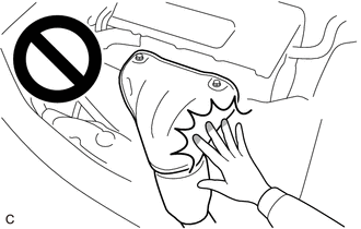
To prevent burns, do not touch the engine, exhaust manifold or other high temperature components while the engine is hot.
PROCEDURE

 1. PRECAUTION
|
|
|
2. DISCHARGE FUEL SYSTEM PRESSURE
51473C 3.REMOVE ENGINE SIDE COVER RH
51474B 4.REMOVE ENGINE SIDE COVER LH
5.RELEASE PARKING BRAKE
6.DISCONNECT CABLE FROM NEGATIVE BATTERY TERMINAL
7.REMOVE FRONT BUMPER ASSEMBLY
for Standard
Click hereVehicle Exterior>EXTERIOR PANELS / TRIM>FRONT BUMPER (for Standard)>REMOVAL
for Aero Type
Click hereVehicle Exterior>EXTERIOR PANELS / TRIM>FRONT BUMPER (for Aero Type)>REMOVAL
51410 8.REMOVE NO. 1 ENGINE UNDER COVER ASSEMBLY
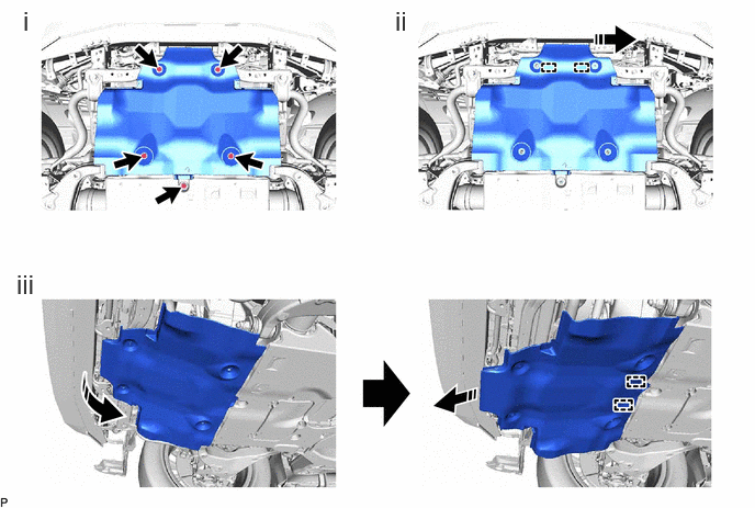

|
Remove in this Direction | - | - |
Remove the 5 bolts.
Move the side of the No. 1 engine under cover assembly facing the front of the vehicle toward the LH side and detach the temporary holding guide.
Remove the No. 1 engine under cover assembly while detaching the 2 temporary holding guides of the No. 1 engine under cover assembly as shown in the illustration.
51420 9.REMOVE NO. 2 ENGINE UNDER COVER ASSEMBLY
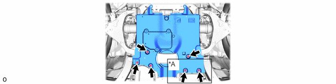
| *A | w/ Cover | - | - |
51430A 10.REMOVE FRAME UNDER COVER ASSEMBLY RH
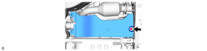
51450C 11.REMOVE FRAME UNDER COVER ASSEMBLY LH (w/ Cover)
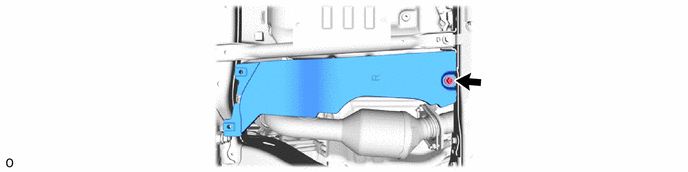
51440 12.REMOVE OIL PAN PROTECTOR ASSEMBLY
13.REMOVE FRONT WHEEL
53782 14.REMOVE FRONT FENDER APRON TRIM PACKING A
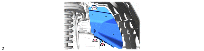
53783 15.REMOVE FRONT FENDER APRON TRIM PACKING B
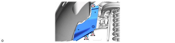
53784 16.REMOVE FRONT FENDER APRON TRIM PACKING C
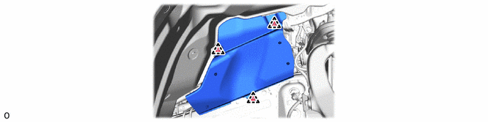
53785B 17.REMOVE FRONT FENDER APRON TRIM PACKING D
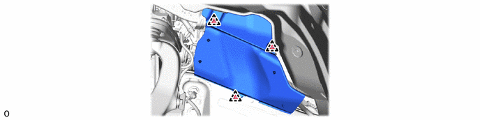
18.DRAIN ENGINE OIL
19.DRAIN ENGINE COOLANT
20.DRAIN COOLANT (for Intercooler)
21.DRAIN AUTOMATIC TRANSMISSION FLUID
16400 22.REMOVE RADIATOR ASSEMBLY
55708 23.REMOVE COWL TOP VENTILATOR LOUVER SUB-ASSEMBLY
53341B 24.REMOVE HOOD INSULATOR
85370 25.DISCONNECT WINDSHIELD WASHER HOSE ASSEMBLY
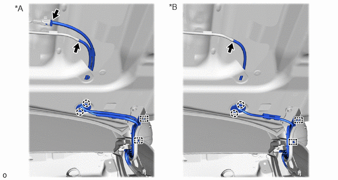
| *A | w/ Heater | *B | w/o Heater |
53301 26.REMOVE HOOD SUB-ASSEMBLY
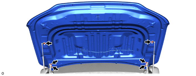
53525 27.REMOVE HOOD LOCK RELEASE LEVER PROTECTOR
53510 28.REMOVE HOOD LOCK ASSEMBLY
53629 29.REMOVE HOOD LOCK CONTROL CABLE COVER
82111 30.DISCONNECT ENGINE ROOM MAIN WIRE
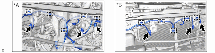
| *A | for LHD | *B | for RHD |
52611 31.REMOVE FRONT BUMPER ENERGY ABSORBER
|
|
·
for Standard Click here(
·
for Aero Type Click here( |
52521 32.REMOVE FRONT BUMPER CENTER UPPER RETAINER
|
|
·
for Standard Click here(
·
for Aero Type Click here( |
88710E 33.REMOVE AIR CONDITIONING TUBE AND ACCESSORY ASSEMBLY AND NO. 2 AIR CONDITIONING TUBE AND ACCESSORY ASSEMBLY
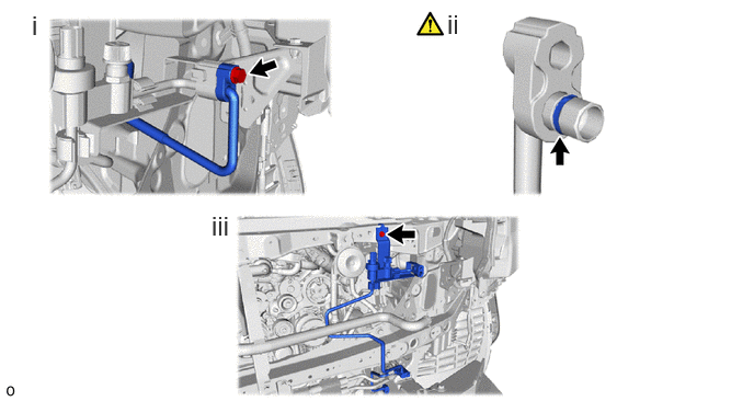
Remove the bolt and cooler refrigerant liquid pipe A.
Remove the O-ring from the cooler refrigerant liquid pipe A.
- NOTICE:
-
Seal the openings of the disconnected parts using vinyl tape to prevent moisture and foreign matter from entering them.
Remove the bolt and air conditioning tube and accessory assembly and No. 2 air conditioning tube and accessory assembly.
53209B 34.REMOVE HOOD LOCK SUPPORT BRACE SUB-ASSEMBLY
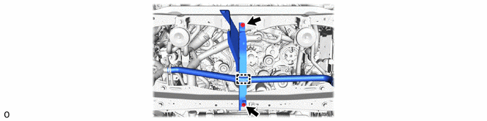
53205 35.REMOVE UPPER RADIATOR SUPPORT SUB-ASSEMBLY
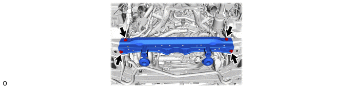
57161C 36.REMOVE FRONT CROSS MEMBER
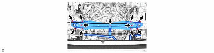
16267C 37.DISCONNECT NO. 4 WATER BY-PASS HOSE
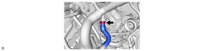
38.REMOVE OIL COOLER TUBE AND OIL COOLER HOSE WITH OIL COOLER ASSEMBLY
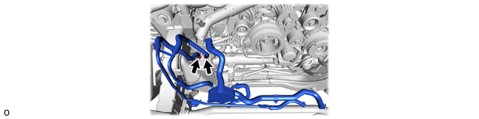
162A0 39.DISCONNECT NO. 4 WATER BY-PASS HOSE ASSEMBLY
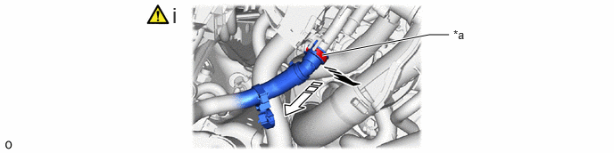
| *a | Retainer | - | - |
|
|
Pull out |

|
Pull off |
Disconnect the No. 4 water by-pass hose assembly connector from the water by-pass hose assembly.
- NOTICE:
-
Remove any foreign matter on the water by-pass hose assembly and No. 4 water by-pass hose assembly connector before performing this work.
1. Pull out the retainer to disengage the lock claws and pull off the No. 4 water by-pass hose assembly connector.
2. Check that there is no foreign matter on the sealing surfaces of the disconnected water lines. Clean them if necessary.
3. Cover the disconnected No. 4 water by-pass hose assembly connector with a plastic bag to prevent damage and contamination.
51478C 40.REMOVE UPPER ENGINE SIDE UNDER COVER PLATE LH
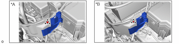
| *A | for LHD | *B | for RHD |
51470C 41.REMOVE REAR ENGINE SIDE UNDER COVER ASSEMBLY LH
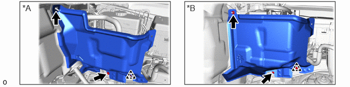
| *A | for LHD | *B | for RHD |
51448M 42.REMOVE ENGINE SIDE UNDER COVER RH
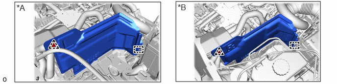
| *A | for LHD | *B | for RHD |
28800 43.REMOVE BATTERY
74410 44.REMOVE BATTERY CARRIER ASSEMBLY
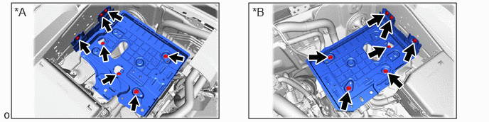
| *A | for LHD | *B | for RHD |
45.DISCONNECT ECM CONNECTOR
82121 46.DISCONNECT ENGINE WIRE
- HINT:
-
After disconnecting the wire harness, secure it with tape or equivalent to keep it out of the way.
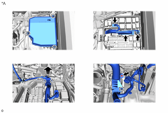
| *A | for LH Side | - | - |
|
|
Remove in this Direction | - | - |
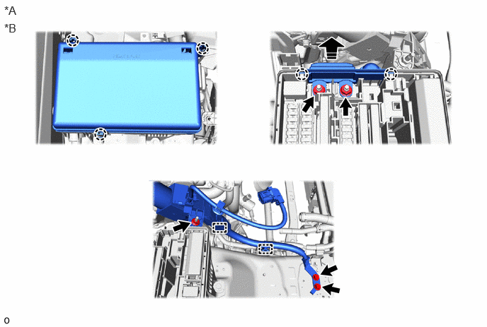
| *A | for LHD | *B | for RH Side |
|
|
Remove in this Direction | - | - |
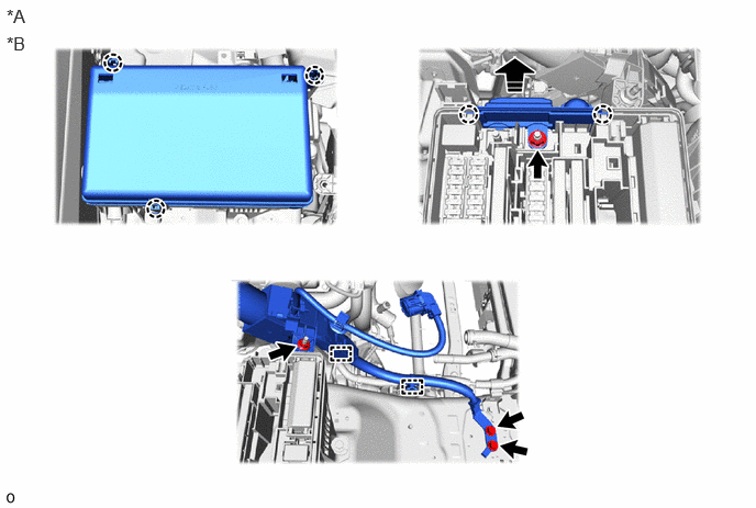
| *A | for RHD | *B | for RH Side |
|
|
Remove in this Direction | - | - |
23826 47.DISCONNECT NO. 1 FUEL VAPOR FEED HOSE
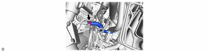
87209 48.DISCONNECT WATER HOSE SUB-ASSEMBLY
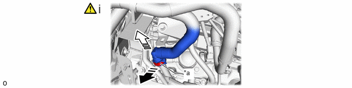
| *a | Retainer | - | - |
|
|
Pull out |
|
Pull off |
Disconnect the water hose sub-assembly connector from the water by-pass hose assembly.
- NOTICE:
-
Remove any foreign matter on the water by-pass hose assembly and water hose sub-assembly connector before performing this work.
1. Pull out the retainer to disengage the lock claws and pull off the water hose sub-assembly connector.
2. Check that there is no foreign matter on the sealing surfaces of the disconnected water lines. Clean them if necessary.
3. Cover the disconnected water hose sub-assembly connector with a plastic bag to prevent damage and contamination.
49.DISCONNECT HEATER WATER HOSE OUTLET A
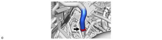
23901 50.DISCONNECT FUEL TUBE SUB-ASSEMBLY
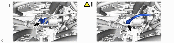
Remove the fuel pipe clamp from the fuel tube connector.
Disconnect the fuel tube sub-assembly.
Click hereEngine / Hybrid System>V35A-FTS (FUEL)>FUEL SYSTEM>PRECAUTION
12262 51.REMOVE NO. 2 PCV HOSE (NO. 2 VENTILATION HOSE)
17311 52.REMOVE NO. 1 AIR INLET DUCT
23901 53.REMOVE FUEL TUBE SUB-ASSEMBLY
|
|
Click here() |
17312D 54.REMOVE NO. 2 AIR INLET DUCT
1728C 55.REMOVE NO. 6 TURBO INSULATOR
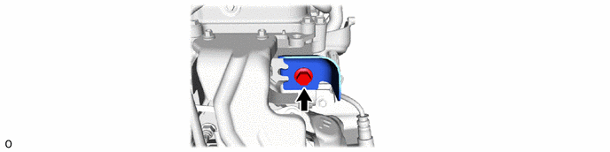
82121 56.DISCONNECT ENGINE WIRE
57.INSTALL ENGINE HANGER
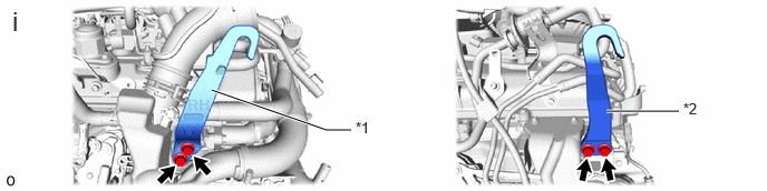
| *1 | No. 1 Engine Hanger | *2 | No. 2 Engine Hanger |
Install the No. 1 engine hanger and No. 2 engine hanger with the 4 bolts as shown in the illustration.
- Torque:
- 43 N*m (438 kgf*cm, 32 ft.*lbf)
- HINT:
-
No. 1 Engine Hanger 12281-70080 No. 2 Engine Hanger 12282-70050 Bolt 91552-F1040
88704 58.DISCONNECT SUCTION HOSE SUB-ASSEMBLY
|
|
Click here() |
44310 59.DISCONNECT VANE PUMP ASSEMBLY
|
|
Click here() |
88704 60.REMOVE SUCTION HOSE SUB-ASSEMBLY
|
|
Click here() |
88711 61.DISCONNECT NO. 1 COOLER REFRIGERANT DISCHARGE HOSE
|
|
Click here() |
62.REMOVE COMPRESSOR ASSEMBLY WITH MAGNET CLUTCH
|
|
Click here() |
27060 63.REMOVE GENERATOR ASSEMBLY
for DENSO Made
Click herePower Source / Network>V35A-FTS (BATTERY / CHARGING)>GENERATOR (for DENSO Made)>REMOVAL
for VALEO Made
Click herePower Source / Network>V35A-FTS (BATTERY / CHARGING)>GENERATOR (for VALEO Made)>REMOVAL
8212B 64.REMOVE NO. 10 ENGINE WIRE
65.REMOVE AUTOMATIC TRANSMISSION ASSEMBLY WITH TRANSFER ASSEMBLY
12371A 66.REMOVE REAR ENGINE MOUNTING INSULATOR
32101 67.REMOVE DRIVE PLATE AND RING GEAR SUB-ASSEMBLY
|
|
Click here() |
19315 68.REMOVE NO. 1 CRANKSHAFT POSITION SENSOR PLATE
69.REMOVE ENGINE ASSEMBLY
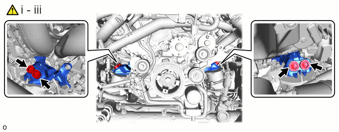
Attach an engine sling device and hang the engine with a chain block.
Using a 17 mm hexagon wrench, remove the 4 hexagon socket head cap bolts.
Remove the engine assembly by operating the engine sling device and chain block.
- NOTICE:
-
·
Make sure that the engine is clear of all wiring and hoses.
·While lowering the engine from the vehicle, do not allow it to contact the vehicle.
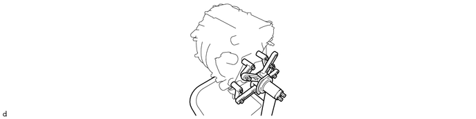
70.INSTALL ENGINE STAND
71.REMOVE ENGINE HANGER
82121 72.REMOVE ENGINE WIRE
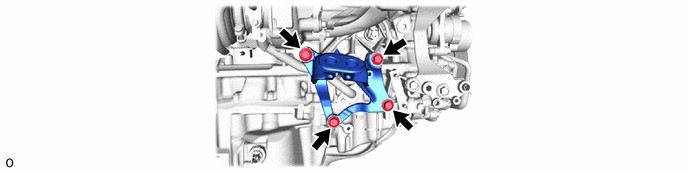
12315 73.REMOVE FRONT NO. 1 ENGINE MOUNTING BRACKET LH
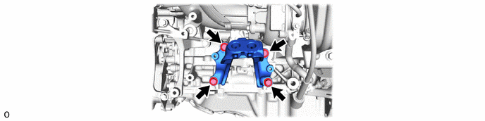
12311 74.REMOVE FRONT NO. 1 ENGINE MOUNTING BRACKET RH
12362A 75.REMOVE FRONT ENGINE MOUNTING INSULATOR LH
- HINT:
-
Perform this procedure only when replacement of the front engine mounting insulator LH is necessary.
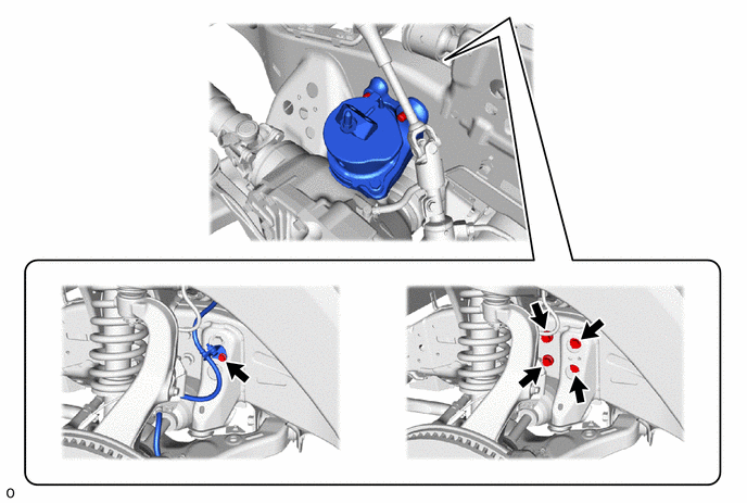
12361E 76.REMOVE FRONT ENGINE MOUNTING INSULATOR RH
- HINT:
-
Perform this procedure only when replacement of the front engine mounting insulator RH is necessary.