Home › Drivetrain › JF2BM (TRANSFER / 4WD / AWD) › TRANSFER SYSTEM
RM38G0E _52 Drivetrain _100437 JF2BM TRANSFER / 4WD / AWD _0467431 TRANSFER SYSTEM J

JF2BM TRANSFER / 4WD / AWD  TRANSFER SYSTEM  Shift Motor Circuit  


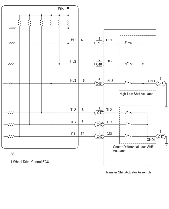
WIRING DIAGRAM
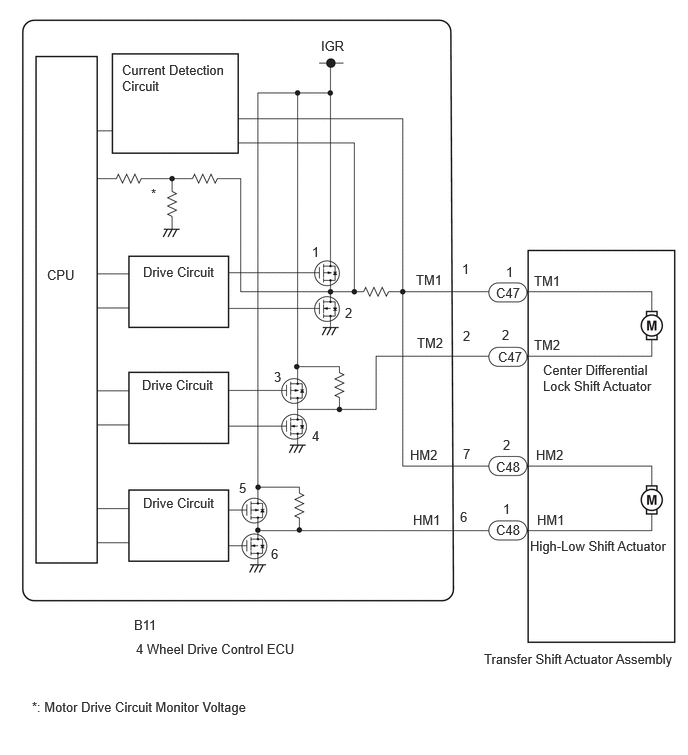
C456051E01
5.594,5.333 6.052,5.531 0.458,0.198 10 false HM1 5.583,4.656 6.042,4.854 0.458,0.198 10 false HM2 4.302,5.333 4.76,5.531 0.458,0.198 10 false HM1 4.271,4.656 4.729,4.854 0.458,0.198 10 false HM2 5.167,5.438 5.625,5.635 0.458,0.198 10 false C48 5.167,4.781 5.625,4.979 0.458,0.198 10 false C48 1.396,6.427 1.854,6.625 0.458,0.198 10 false B11 4.792,5.302 4.948,5.5 0.156,0.198 10 false 6 4.823,4.646 4.979,4.844 0.156,0.198 10 false 7 5.24,5.219 5.396,5.417 0.156,0.198 10 false 1 5.24,4.552 5.396,4.75 0.156,0.198 10 false 2 5.521,5.604 6.99,5.906 1.469,0.302 10 false High-Low Shift Actuator 5.656,3.771 6.854,4.302 1.198,0.531 10 false Center Differential Lock Shift Actuator 5.042,6.781 7.094,7.052 2.052,0.271 10 false Transfer Shift Actuator Assembly 5.563,2.844 6.021,3.042 0.458,0.198 10 false TM1 5.563,3.51 6.021,3.708 0.458,0.198 10 false TM2 4.333,2.833 4.792,3.031 0.458,0.198 10 false TM1 4.344,3.49 4.802,3.688 0.458,0.198 10 false TM2 5.167,2.969 5.625,3.167 0.458,0.198 10 false C47 5.188,3.635 5.646,3.833 0.458,0.198 10 false C47 5.271,2.75 5.427,2.948 0.156,0.198 10 false 1 5.229,3.406 5.385,3.604 0.156,0.198 10 false 2 1.417,6.677 3.281,6.896 1.865,0.219 10 false 4 Wheel Drive Control ECU 4.813,2.719 4.969,2.917 0.156,0.198 10 false 1 4.823,3.417 4.979,3.615 0.156,0.198 10 false 2 1.271,0.646 2.375,1.125 1.104,0.479 10 false Current Detection Circuit 1.49,2.75 2.365,2.917 0.875,0.167 10 false Drive Circuit 1.49,5.156 2.417,5.344 0.927,0.188 10 false Drive Circuit 1.479,3.927 2.385,4.135 0.906,0.208 10 false Drive Circuit 0.49,2.781 0.948,2.979 0.458,0.198 10 false CPU 1.573,1.938 1.729,2.135 0.156,0.198 10 false * 0.333,7.281 2.813,7.479 2.479,0.198 10 false *: Motor Drive Circuit Monitor Voltage 3.344,0.396 3.802,0.594 0.458,0.198 10 false IGR 3.25,2.542 3.406,2.74 0.156,0.198 10 false 1 3.594,3.177 3.781,3.385 0.188,0.208 10 false 2 2.854,3.844 3.01,4.042 0.156,0.198 10 false 3 3.25,4.458 3.406,4.656 0.156,0.198 10 false 4 2.49,5 2.646,5.198 0.156,0.198 10 false 5 2.823,5.688 2.979,5.885 0.156,0.198 10 false 6

C456418E01
6.271,3.354 6.729,3.552 0.458,0.198 10 false GND 6.771,3.25 6.927,3.448 0.156,0.198 10 false 6 4.552,3.344 5.01,3.542 0.458,0.198 10 false HL3 4.521,2.5 4.979,2.698 0.458,0.198 10 false HL2 4.5,1.615 4.958,1.813 0.458,0.198 10 false HL1 3.01,1.604 3.333,1.802 0.323,0.198 10 false HL1 2.979,2.521 3.323,2.719 0.344,0.198 10 false HL2 2.979,3.333 3.333,3.531 0.354,0.198 10 false HL3 4.177,1.552 4.344,1.75 0.167,0.198 10 false 3 4.177,2.438 4.344,2.635 0.167,0.198 10 false 5 4.177,3.271 4.344,3.469 0.167,0.198 10 false 4 3.438,1.615 3.646,1.813 0.208,0.198 10 false 6 3.458,2.51 3.667,2.708 0.208,0.198 10 false 5 3.438,3.333 3.646,3.531 0.208,0.198 10 false 15 5.063,3.896 6.552,4.156 1.49,0.26 10 false High-Low Shift Actuator 6.219,5.844 6.833,6.042 0.615,0.198 10 false GND1 4.792,6.146 6.542,6.615 1.75,0.469 10 false Center Differential Lock Shift Actuator 4.521,5.094 4.979,5.292 0.458,0.198 10 false TL3 4.521,5.594 4.979,5.792 0.458,0.198 10 false CDL 6.76,5.5 6.917,5.698 0.156,0.198 10 false 4 4.51,4.573 4.969,4.771 0.458,0.198 10 false TL2 2.99,4.573 3.448,4.771 0.458,0.198 10 false TL2 2.979,5.094 3.438,5.292 0.458,0.198 10 false TL3 3.021,5.594 3.479,5.792 0.458,0.198 10 false P1 3.469,4.573 3.677,4.771 0.208,0.198 10 false 8 3.458,5.083 3.667,5.281 0.208,0.198 10 false 7 3.417,5.583 3.625,5.781 0.208,0.198 10 false 17 4.188,4.531 4.396,4.729 0.208,0.198 10 false 6 4.177,5.021 4.344,5.219 0.167,0.198 10 false 5 4.177,5.531 4.333,5.729 0.156,0.198 10 false 3 6.677,3.469 7.135,3.667 0.458,0.198 10 false C48 4.104,5.208 4.563,5.406 0.458,0.198 10 false C47 4.073,2.646 4.531,2.844 0.458,0.198 10 false C48 4.094,1.75 4.552,1.948 0.458,0.198 10 false C48 4.104,5.719 4.563,5.917 0.458,0.198 10 false C47 4.115,4.698 4.573,4.896 0.458,0.198 10 false C47 4.469,7.229 6.615,7.49 2.146,0.26 10 false Transfer Shift Actuator Assembly 0.448,6.448 0.76,6.646 0.313,0.198 10 false B8 0.438,6.781 2.292,7.01 1.854,0.229 10 false 4 Wheel Drive Control ECU 4.063,3.458 4.521,3.656 0.458,0.198 10 false C48 6.698,5.719 7.156,5.917 0.458,0.198 10 false C47 2.458,0.271 2.917,0.469 0.458,0.198 10 false IGR

CAUTION / NOTICE / HINT

NOTICE:

When the vehicle is stopped, mode switching may be unavailable due to the phase of the transfer assembly powertrain. There is no malfunction if mode switching is available after the vehicle is moved.


PROCEDURE

1.CONFIRM PROBLEM SYMPTOM
a.

Confirm the problem symptoms.

Result:
Result Proceed to

Blinking: Blinks at 0.5 second intervals (0.5 seconds on and 0.5 seconds off)

The 4LO indicator light continues to blink after operation of the transfer position switch A
The center differential lock indicator light continues to blink after operation of the center differential lock switch (transfer position switch) B


A

2.CHECK HARNESS AND CONNECTOR (4 WHEEL DRIVE CONTROL ECU - HIGH-LOW SHIFT ACTUATOR (TRANSFER SHIFT ACTUATOR ASSEMBLY))

B

5.CHECK HARNESS AND CONNECTOR (4 WHEEL DRIVE CONTROL ECU - CENTER DIFFERENTIAL LOCK SHIFT ACTUATOR (TRANSFER SHIFT ACTUATOR ASSEMBLY))
2.CHECK HARNESS AND CONNECTOR (4 WHEEL DRIVE CONTROL ECU - HIGH-LOW SHIFT ACTUATOR (TRANSFER SHIFT ACTUATOR ASSEMBLY))
a.

Disconnect the B11 4 wheel drive control ECU connector.


b.

Disconnect the C48 high-low shift actuator (transfer shift actuator assembly) connector.


c.

Measure the resistance according to the value(s) in the table below.

Standard Resistance:
Tester Connection Condition Specified Condition

Click Location & Routing(B11,C48)Location & Routing

Click Connector(B11)Instrument Panel>Engine Room Main Wire / Heater Blower Wire>4 Wheel Drive Control ECU

Click Connector(C48)Engine Compartment>Connecting Wire / Cooling Fan Wire / Engine Wire / Fuel Pump Motor Wire / No. 1 Connecting Wire / No. 10 Engine Wire / No. 2 Connecting Wire / No. 3 Connecting Wire / No. 4 Connecting Wire / Sensor Wire / Turbocharger Wire>Transfer Assembly

B11-6 (HM1) - C48-1 (HM1) Always Below 1 Ω
B11-7 (HM2) - C48-2 (HM2) Always Below 1 Ω
B11-6 (HM1) or C48-1 (HM1) - B11-7 (HM2) or C48-2 (HM2) Always 10 kΩ or higher


d.

Connect the C48 high-low shift actuator (transfer shift actuator assembly) connector.


e.

Connect the B11 4 wheel drive control ECU connector.


Result:
Proceed to
OK
NG


OK

3.CHECK HARNESS AND CONNECTOR (4 WHEEL DRIVE CONTROL ECU - HIGH-LOW SHIFT ACTUATOR (TRANSFER SHIFT ACTUATOR ASSEMBLY))

NG

REPAIR OR REPLACE HARNESS OR CONNECTOR

3.CHECK HARNESS AND CONNECTOR (4 WHEEL DRIVE CONTROL ECU - HIGH-LOW SHIFT ACTUATOR (TRANSFER SHIFT ACTUATOR ASSEMBLY))
a.

Disconnect the B8 4 wheel drive control ECU connector.


b.

Disconnect the C48 high-low shift actuator (transfer shift actuator assembly) connector.


c.

Measure the resistance according to the value(s) in the table below.

Standard Resistance:
Tester Connection Condition Specified Condition

Click Location & Routing(B8,C48)Location & Routing

Click Connector(B8)Instrument Panel>Engine Room Main Wire / Heater Blower Wire>4 Wheel Drive Control ECU

Click Connector(C48)Engine Compartment>Connecting Wire / Cooling Fan Wire / Engine Wire / Fuel Pump Motor Wire / No. 1 Connecting Wire / No. 10 Engine Wire / No. 2 Connecting Wire / No. 3 Connecting Wire / No. 4 Connecting Wire / Sensor Wire / Turbocharger Wire>Transfer Assembly

B8-6 (HL1) - C48-3 (HL1) Always Below 1 Ω
B8-5 (HL2) - C48-5 (HL2) Always Below 1 Ω
C48-6 (GND) - Body ground Always Below 1 Ω
B8-6 (HL1) or C48-3 (HL1) - Body ground Always 10 kΩ or higher
B8-5 (HL2) or C48-5 (HL2) - Body ground Always 10 kΩ or higher


d.

Connect the C48 high-low shift actuator (transfer shift actuator assembly) connector.


e.

Connect the B8 4 wheel drive control ECU connector.


Result:
Proceed to
OK
NG


OK

4.INSPECT HIGH-LOW SHIFT ACTUATOR (TRANSFER SHIFT ACTUATOR ASSEMBLY)

NG

REPAIR OR REPLACE HARNESS OR CONNECTOR

4.INSPECT HIGH-LOW SHIFT ACTUATOR (TRANSFER SHIFT ACTUATOR ASSEMBLY)
a.

Inspect the high-low shift actuator (transfer shift actuator assembly).

Click hereDrivetrain>JF2BM (TRANSFER / 4WD / AWD)>TRANSFER ASSEMBLY>INSPECTION


Result:
Proceed to
OK
NG


OK

NG

REPLACE TRANSFER SHIFT ACTUATOR ASSEMBLY

5.CHECK HARNESS AND CONNECTOR (4 WHEEL DRIVE CONTROL ECU - CENTER DIFFERENTIAL LOCK SHIFT ACTUATOR (TRANSFER SHIFT ACTUATOR ASSEMBLY))
a.

Disconnect the B11 4 wheel drive control ECU connector.


b.

Disconnect the C47 center differential lock shift actuator (transfer shift actuator assembly) connector.


c.

Measure the resistance according to the value(s) in the table below.

Standard Resistance:
Tester Connection Condition Specified Condition

Click Location & Routing(B11,C47)Location & Routing

Click Connector(B11)Instrument Panel>Engine Room Main Wire / Heater Blower Wire>4 Wheel Drive Control ECU

Click Connector(C47)Engine Compartment>Connecting Wire / Cooling Fan Wire / Engine Wire / Fuel Pump Motor Wire / No. 1 Connecting Wire / No. 10 Engine Wire / No. 2 Connecting Wire / No. 3 Connecting Wire / No. 4 Connecting Wire / Sensor Wire / Turbocharger Wire>Transfer Assembly

B11-1 (TM1) - C47-1 (TM1) Always Below 1 Ω
B11-2 (TM2) - C47-2 (TM2) Always Below 1 Ω
B11-1 (TM1) or C47-1 (TM1) - B11-2 (TM2) or C47-2 (TM2) Always 10 kΩ or higher


d.

Connect the C47 center differential lock shift actuator (transfer shift actuator assembly) connector.


e.

Connect the B11 4 wheel drive control ECU connector.


Result:
Proceed to
OK
NG


OK

6.CHECK HARNESS AND CONNECTOR (4 WHEEL DRIVE CONTROL ECU - CENTER DIFFERENTIAL LOCK SHIFT ACTUATOR (TRANSFER SHIFT ACTUATOR ASSEMBLY))

NG

REPAIR OR REPLACE HARNESS OR CONNECTOR

6.CHECK HARNESS AND CONNECTOR (4 WHEEL DRIVE CONTROL ECU - CENTER DIFFERENTIAL LOCK SHIFT ACTUATOR (TRANSFER SHIFT ACTUATOR ASSEMBLY))
a.

Disconnect the B8 4 wheel drive control ECU connector.


b.

Disconnect the C47 center differential lock shift actuator (transfer shift actuator assembly) connector.


c.

Measure the resistance according to the value(s) in the table below.

Standard Resistance:
Tester Connection Condition Specified Condition

Click Location & Routing(B8,C47)Location & Routing

Click Connector(B8)Instrument Panel>Engine Room Main Wire / Heater Blower Wire>4 Wheel Drive Control ECU

Click Connector(C47)Engine Compartment>Connecting Wire / Cooling Fan Wire / Engine Wire / Fuel Pump Motor Wire / No. 1 Connecting Wire / No. 10 Engine Wire / No. 2 Connecting Wire / No. 3 Connecting Wire / No. 4 Connecting Wire / Sensor Wire / Turbocharger Wire>Transfer Assembly

B8-8 (TL2) - C47-6 (TL2) Always Below 1 Ω
B8-7 (TL3) - C47-5 (TL3) Always Below 1 Ω
B8-17 (P1) - C47-3 (CDL) Always Below 1 Ω
C47-4 (GND1) - Body ground Always Below 1 Ω
B8-8 (TL2) or C47-6 (TL2) - Body ground Always 10 kΩ or higher
B8-7 (TL3) or C47-5 (TL3) - Body ground Always 10 kΩ or higher
B8-17 (P1) or C47-3 (CDL) - Body ground Always 10 kΩ or higher


d.

Connect the C47 center differential lock shift actuator (transfer shift actuator assembly) connector.


e.

Connect the B8 4 wheel drive control ECU connector.


Result:
Proceed to
OK
NG


OK

7.INSPECT CENTER DIFFERENTIAL LOCK SHIFT ACTUATOR (TRANSFER SHIFT ACTUATOR ASSEMBLY)

NG

REPAIR OR REPLACE HARNESS OR CONNECTOR

7.INSPECT CENTER DIFFERENTIAL LOCK SHIFT ACTUATOR (TRANSFER SHIFT ACTUATOR ASSEMBLY)
a.

Inspect the center differential lock shift actuator (transfer shift actuator assembly).

Click hereDrivetrain>JF2BM (TRANSFER / 4WD / AWD)>TRANSFER ASSEMBLY>INSPECTION


Result:
Proceed to
OK
NG


OK

NG

REPLACE TRANSFER SHIFT ACTUATOR ASSEMBLY