METER / GAUGE / DISPLAY METER / GAUGE SYSTEM B151287 Lost Communication with Steering Switch Control Module Missing Message
DESCRIPTION
Combination meter assembly performs the communication with the multiplex network steering ECU by CXPI communication.
When the communication with the multiplex network steering ECU stops, Combination meter assembly outputs B151287.
| DTC No. | Detection Item | DTC Detection Condition | Trouble Area |
|---|---|---|---|
| B151287 | Lost Communication with Steering Switch Control Module Missing Message | Diagnosis Condition:
·
Ignition switch ON
·
IG power source voltage is 9.5 V or more Malfunction Status: No communication with multiplex network steering ECU Malfunction Time: 10 seconds or more |
·
Harness or connector
·
Spiral cable sub-assembly
·
Multiplex network steering ECU
·
Combination meter assembly |
WIRING DIAGRAM
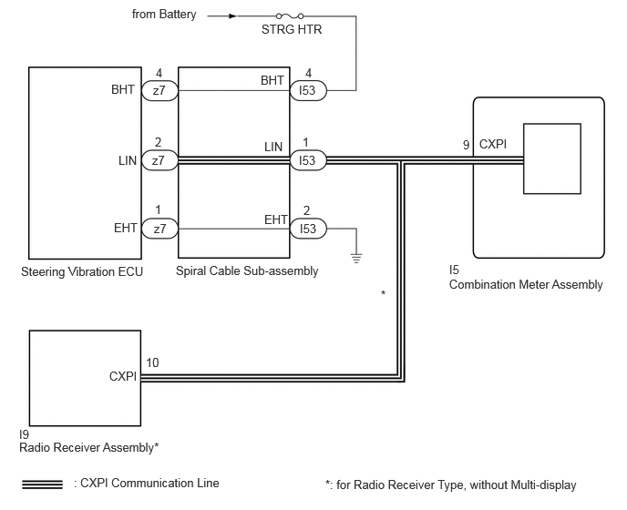
CAUTION / NOTICE / HINT
- NOTICE:
-
·
When replacing the combination meter assembly, always replace it with a new one. If a combination meter assembly which was installed to another vehicle is used, the information stored in it will not match the information from the vehicle and a DTC may be stored.
·The vehicle is equipped with a Supplemental Restraint System (SRS) which includes components such as airbags. Before servicing (including removal or installation of parts), be sure to read the precaution for Supplemental Restraint System.
Click hereVehicle Interior>SUPPLEMENTAL RESTRAINT SYSTEMS>AIRBAG SYSTEM>PRECAUTION
·When the combination meter assembly is replaced, update the ECU security key.
Click hereGeneral>SETUP>WHEN REPLACING OR REMOVING/INSTALLING PARTS>UPDATE ECU SECURITY KEY
·Inspect the fuses of circuits related to this system before performing the following procedure.
PROCEDURE
Disconnect the I53 spiral cable sub-assembly connector.
Using an oscilloscope, check the waveform.
- NOTICE:
-
The wave pattern changes according to CXPI communication signal.
- OK:
-
Tester Connection Switch Condition Specified Condition Click Location & Routing(I53)Location & Routingewd_type=routing;type=c;code=I53
I53-1 (LIN) - Body ground Ignition switch ON Pulse generation
- Result:
-
Proceed to OK NG
OK
NG
Disconnect the I53 spiral cable sub-assembly connector.
Measure the voltage according to the value(s) in the table below.
- Standard Voltage:
-
Tester Connection Condition Specified Condition Click Location & Routing(I53)Location & Routingewd_type=routing;type=c;code=I53
I53-4 (BHT) - Body ground Always 11 to 14 V
Measure the resistance according to the value(s) in the table below.
- Standard Resistance:
-
Tester Connection Condition Specified Condition Click Location & Routing(I53)Location & Routingewd_type=routing;type=c;code=I53
I53-2 (EHT) - Body ground Always Below 1 Ω
- Result:
-
Proceed to OK NG
OK
NG
Click hereVehicle Interior>SUPPLEMENTAL RESTRAINT SYSTEMS>SPIRAL CABLE>INSPECTION
- Result:
-
Proceed to OK NG
OK
NG
Check vehicle condition.
- Result:
-
Result Proceed to for Radio Receiver Type, without Multi-display A except Radio Receiver Type, without Multi-display B
A
B
Disconnect the I53 spiral cable sub-assembly connector.
Disconnect the I10 radio receiver assembly connector.
Using an oscilloscope, check the waveform.
- NOTICE:
-
The wave pattern changes according to CXPI communication signal.
- OK:
-
Tester Connection Switch Condition Specified Condition Click Location & Routing(I53)Location & Routingewd_type=routing;type=c;code=I53
I53-1 (LIN) - Body ground Ignition switch ON Pulse generation
- Result:
-
Proceed to OK NG
OK
Click hereAudio / Visual / Telematics>AUDIO / VIDEO>RADIO RECEIVER (for Radio Receiver Type)>REMOVAL
NG
Disconnect the I5 combination meter assembly connector.
Disconnect the I53 spiral cable sub-assembly connector.
for Radio Receiver Type, without Multi-display:
Disconnect the I10 radio receiver assembly connector.
Measure the resistance according to the value(s) in the table below.
- Standard Resistance:
-
Tester Connection Condition Specified Condition Click Location & Routing(I5,I53)Location & Routingewd_type=routing;type=c,c;code=I5,I53
I5-9 (CXPI) - I53-1 (LIN) Always Below 1 Ω I5-9 (CXPI) or I53-1 (LIN) - Body ground Always 10 kΩ or higher
- Result:
-
Proceed to OK NG
OK
NG