SUPPLEMENTAL RESTRAINT SYSTEMS SPIRAL CABLE REMOVAL
CAUTION / NOTICE / HINT
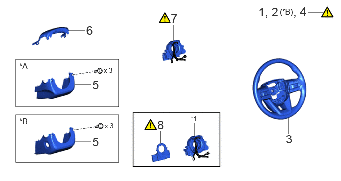
| Procedure | Part Name Code |

|

|

|
|
|---|---|---|---|---|---|
| 1 | PRECAUTION | - | ( ) |
- | - |
| 2 | CUSTOMIZE POWER TILT AND POWER TELESCOPIC STEERING COLUMN SYSTEM | - | () |
- | - |
| 3 | STEERING WHEEL ASSEMBLY | 45100 | - | - | - |
| 4 | INSPECT SPIRAL CABLE SUB-ASSEMBLY | - | () |
- | - |
| 5 | LOWER STEERING COLUMN COVER SUB-ASSEMBLY | 45024 | - | - | - |
| 6 | UPPER STEERING COLUMN COVER | 45286B | - | - | - |
| 7 | SPIRAL CABLE WITH SENSOR SUB-ASSEMBLY | - | () |
- | - |
| 8 | STEERING SENSOR | 89245B | () |
- | - |
| *A | for Manual Tilt and Manual Telescopic Steering Column | *B | for Power Tilt and Power Telescopic Steering Column |
| *1 | SPIRAL CABLE SUB-ASSEMBLY | - | - |
CAUTION / NOTICE / HINT
The necessary procedures (adjustment, calibration, initialization or registration) that must be performed after parts are removed, installed or replaced during the spiral cable with sensor sub-assembly or spiral cable sub-assembly removal/installation are shown below.
| Replaced Part or Performed Procedure | Necessary Procedures | Effect/Inoperative Function When Necessary Procedures are not Performed | Link |
|---|---|---|---|
| Disconnect cable from negative battery terminal | Memorize steering angle neutral point | Parking assist monitor system | () |
| Multi-terrain monitor system | () |
||
| Panoramic view monitor system | () |
||
| Steering sensor (Including removal and installation) | Steering angle neutral point | Panoramic view monitor system | () |
| Parking assist monitor system | () |
||
| Steering angle setting | Panoramic view monitor system | () |
|
| Parking assist monitor system | () |
- HINT:
-
·
When the cable is disconnected/reconnected to the battery terminal, systems temporarily stop operating. However, each system has a function that completes learning the first time the system is used.
-Learning completes when vehicle is driven
Effect/Inoperative Function When Necessary Procedures are not Performed Necessary Procedures Link Stop and start system Drive the vehicle until stop and start control is permitted (approximately 5 to 60 minutes) ( )Lighting system (EXT) Cornering lights Drive the vehicle straight ahead at 35 km/h (22 mph) or more for 5 seconds or more. ( )Pre-collision system Lane tracing assist system Lane departure alert system Adaptive high beam system
-Learning completes when vehicle is operated normally
Effect/Inoperative Function When Necessary Procedures are not Performed Necessary Procedures Link Power back door system Fully close the back door by hand.
- HINT:
-
Initialization is not necessary if the above procedures are performed while the back door is closed.
( )Air conditioning system After the ignition switch is turned to ON, the servo motor and expansion valve standard position is recognized. -
·Use the same procedure for the LHD and RHD vehicles.
·The procedure listed below is for the LHD vehicles.
PROCEDURE

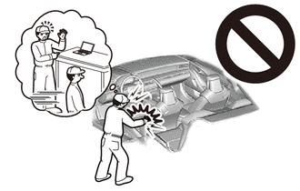
 1. PRECAUTION
|
|
|
2. CUSTOMIZE POWER TILT AND POWER TELESCOPIC STEERING COLUMN SYSTEM (for Power Tilt and Power Telescopic Steering Column)
|
|
Click here() |
45100 3.REMOVE STEERING WHEEL ASSEMBLY
4.INSPECT SPIRAL CABLE SUB-ASSEMBLY
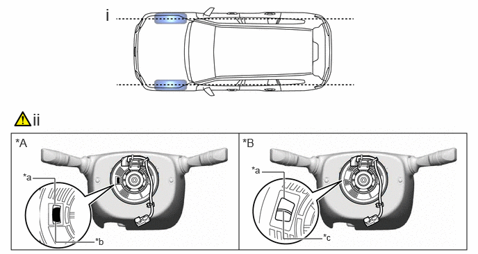
| *A | Colored Roller (Visible Type) | *B | Flat Cable (Visible Type) |
| *a | Check Window | *b | Colored Roller |
| *c | Top of Flat Cable U-turn | - | - |
Check that the front wheels are aligned facing straight ahead.
Check that the spiral cable sub-assembly is in the center position.
- OK:
-
The connector is at the top.
-
The colored roller or the top of the flat cable U-turn can be checked from the check window.
- NOTICE:
-
If the result is not as specified, it is possible that the spiral cable sub-assembly is broken. Replace the spiral cable sub-assembly with a new one.
45024 5.REMOVE LOWER STEERING COLUMN COVER SUB-ASSEMBLY
for Manual Tilt and Manual Telescopic Steering Column:
for Power Tilt and Power Telescopic Steering Column:
45286B 6.REMOVE UPPER STEERING COLUMN COVER
7.REMOVE SPIRAL CABLE WITH SENSOR SUB-ASSEMBLY
|
|
|
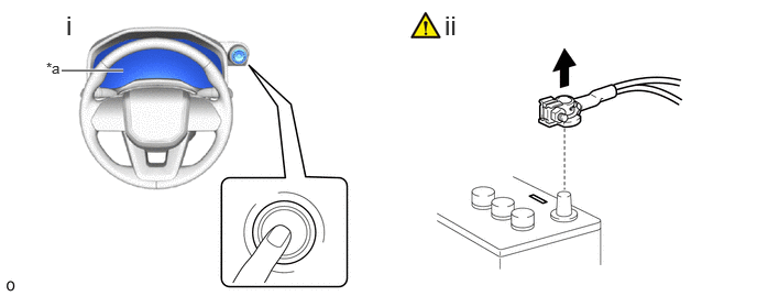
| *a | Turns off | - | - |
Check that the ignition switch is off.
Check that the cable is disconnected from the negative (-) battery terminal.
- CAUTION:
-
·
Wait at least 60 seconds after disconnecting the cable from the negative (-) battery terminal to disable the SRS system.
·If the airbag deploys for any reason, it may cause a serious accident.
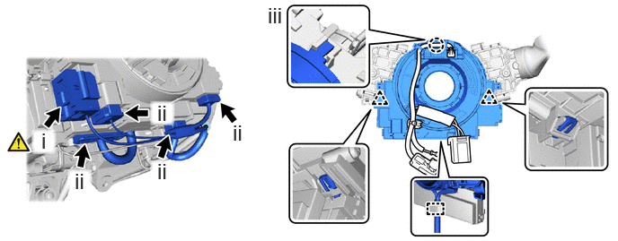
Disconnect the airbag connector.
- NOTICE:
-
When disconnecting any airbag connector, take care not to damage the airbag wire harness.
- HINT:
-
Refer to How to Connect or Disconnect Airbag Connector: Click hereVehicle Interior>SUPPLEMENTAL RESTRAINT SYSTEMS>AIRBAG SYSTEM>HOW TO CONNECT OR DISCONNECT AIRBAG CONNECTOR
Disconnect the 4 connectors.
Disengage the clamp, claw and clip to remove the spiral cable with sensor sub-assembly.
89245B 8.REMOVE STEERING SENSOR
|
|
|
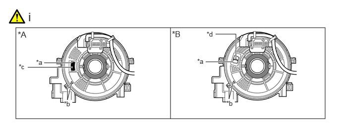
| *A | Colored Roller (Visible Type) | *B | Flat Cable (Visible Type) |
| *a | Check Window | *b | Alignment Mark |
| *c | Colored Roller | *d | Top of Flat Cable U-turn |
Check that the spiral cable sub-assembly is centered.
- HINT:
-
If the spiral cable sub-assembly is not centered, center it.
-
Click hereVehicle Interior>SUPPLEMENTAL RESTRAINT SYSTEMS>SPIRAL CABLE>INSTALLATION
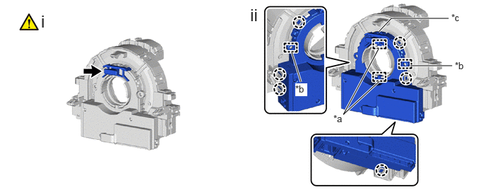
| *a | Guide | *b | Pin |
| *c | Lock Pin | - | - |
Install the lock pin to the steering sensor.
- NOTICE:
-
·
Use the lock pin provided with a new spiral cable sub-assembly.
·Do not remove the lock pin before the steering sensor is installed to the spiral cable sub-assembly.
Disengage the claw, guide and pin to remove the steering sensor from the spiral cable sub-assembly.