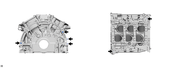
V35A-FTS ENGINE MECHANICAL CYLINDER BLOCK DISASSEMBLY
CAUTION / NOTICE / HINT
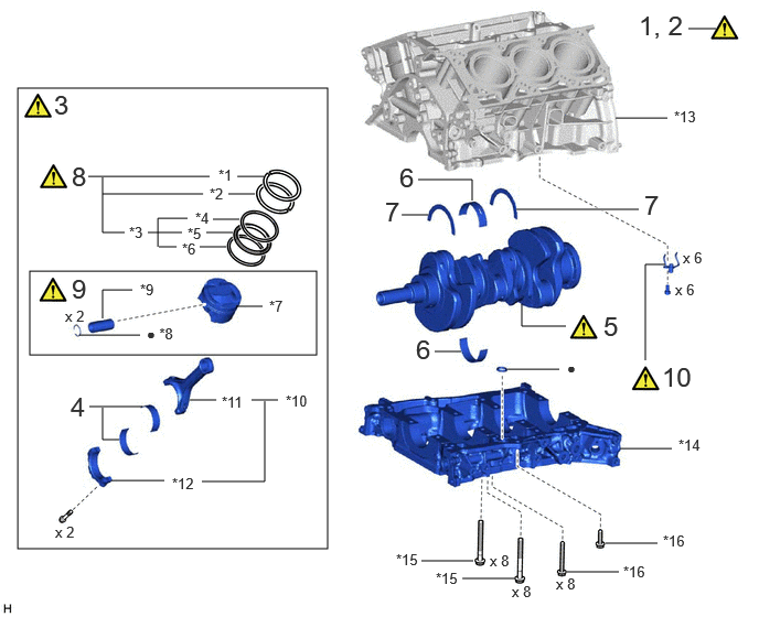
| Procedure | Part Name Code |

|

|

|
|
|---|---|---|---|---|---|
| 1 | INSPECT CONNECTING ROD THRUST CLEARANCE | - | ( ) |
- | - |
| 2 | INSPECT CONNECTING ROD OIL CLEARANCE | - | () |
- | - |
| 3 | PISTON SUB-ASSEMBLY WITH CONNECTING ROD | - | () |
- | - |
| 4 | CONNECTING ROD BEARING | 13041 | - | - | - |
| 5 | CRANKSHAFT | 13411 | () |
- | - |
| 6 | CRANKSHAFT BEARING | 11711 | - | - | - |
| 7 | CRANKSHAFT THRUST WASHER SET | 11011 | - | - | - |
| 8 | PISTON RING SET | 13011 | () |
- | - |
| 9 | PISTON SUB-ASSEMBLY WITH PIN | - | () |
- | - |
| 10 | NO. 1 OIL NOZZLE SUB-ASSEMBLY | 15708 | () |
- | - |
| *1 | NO. 1 COMPRESSION RING | *2 | NO. 2 COMPRESSION RING |
| *3 | OIL RING | *4 | UPPER SIDE RAIL |
| *5 | OIL RING EXPANDER | *6 | LOWER SIDE RAIL |
| *7 | PISTON | *8 | PISTON PIN HOLE SNAP RING |
| *9 | PISTON PIN | *10 | CONNECTING ROD SUB-ASSEMBLY |
| *11 | CONNECTING ROD | *12 | CONNECTING ROD CAP |
| *13 | CYLINDER BLOCK SUB-ASSEMBLY | *14 | CRANKSHAFT BEARING CAP SUB-ASSEMBLY |
| *15 | CRANKSHAFT BEARING CAP SET BOLT | *16 | CRANKSHAFT BEARING CAP BOLT |
| ● | Non-reusable part | - | - |
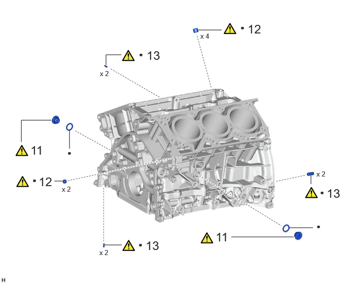
| Procedure | Part Name Code |
|
|
|
|
|---|---|---|---|---|---|
| 11 | CYLINDER BLOCK PLUG WITH HEAD STRAIGHT SCREW | 11432R | () |
- | - |
| 12 | RING PIN | - | () |
- | - |
| 13 | STRAIGHT PIN | - | () |
- | - |
| ● | Non-reusable part | - | - |
CAUTION / NOTICE / HINT
The necessary procedures (adjustment, calibration, initialization, or registration) that must be performed after parts are removed, installed, or replaced during the cylinder block removal/installation are shown below.
| Replaced Part or Performed Procedure | Necessary Procedure | Effect/Inoperative Function when Necessary Procedure not Performed | Link |
|---|---|---|---|
| Battery terminal is disconnected/reconnected | Memorize steering angle neutral point | Parking assist monitor system | () |
| Multi-terrain monitor system | () |
||
| Panoramic view monitor system | () |
||
|
·
Throttle body with motor assembly
·
Cleaning the deposits from the throttle body with motor assembly
·
Cylinder head sub-assembly
·
Camshaft (for intake or exhaust camshaft)
·
Camshaft timing intake gear assembly
·
Camshaft timing exhaust gear assembly
·
Piston
·
Port fuel injector assembly
·
Direct fuel injector assembly
·
Fuel pump assembly (for high pressure side)
·
Spark plug
·
Ignition coil assembly
·
Air leaks from intake system
·
Gas leaks from exhaust system
·
Turbocharger sub-assembly |
Inspection after repairs |
·
Poor idle, etc.
·
Engine start function, etc. |
() |
| Engine assembly | Inspection after repair |
·
Poor idle, etc.
·
Engine start function, etc. |
() |
| Perform road test to allow TCM to learn |
·
Large shift shock
·
Engine overruns |
() |
|
| Piston ring | Inspection after repair |
·
Poor idle, etc.
·
Engine start function, etc. |
() |
|
Heavy Knock History
Initializes the stored history data |
- | () |
|
| Automatic transmission assembly | ECU configuration | - | () |
| Update ECU security key | Vehicle control history (RoB) are stored | () |
|
| Automatic transmission fluid | ATF thermal degradation estimate reset | The value of the Data List item "ATF Thermal Degradation Estimate" is not estimated correctly. | () |
| Front bumper assembly (Including removal and installation) | Front television camera view adjustment | Panoramic view monitor system | () |
- HINT:
-
When the cable is disconnected/reconnected to the battery terminal, systems temporarily stop operating. However, each system has a function that completes learning the first time the system is used.
-
·
Learning completes when vehicle is driven
Effect/Inoperative Function When Necessary Procedures are not Performed Necessary Procedures Link Stop and start system Drive the vehicle until stop and start control is permitted (approximately 5 to 60 minutes). ( )Lighting system (EXT) Cornering lights Drive the vehicle straight ahead at 35 km/h (22 mph) or more for 5 seconds or more. ( )Pre-collision system Lane tracing assist system Lane departure alert system Adaptive high beam system
·Learning completes when vehicle is operated normally
Effect/Inoperative Function When Necessary Procedures are not Performed Necessary Procedures Link Power back door system Fully close the back door by hand.
- HINT:
-
Initialization is not necessary if the above procedures are performed while the back door is closed.
( )Air conditioning system After the ignition switch is turned to ON, the servo motor and expansion valve standard position is recognized. -
- NOTICE:
-
This procedure includes the removal of small-head bolts. Refer to Small-Head Bolts of Basic Repair Hint to identify the small-head bolts.
-
Click hereGeneral>INTRODUCTION>REPAIR INSTRUCTION>PRECAUTION
PROCEDURE

 1.INSPECT CONNECTING ROD THRUST CLEARANCE
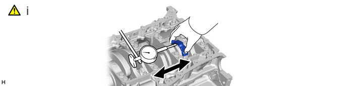
Using a dial indicator, measure the thrust clearance while moving the connecting rod back and forth.
- Standard thrust clearance:
-
0.15 to 0.40 mm (0.00591 to 0.0157 in.)
- Maximum thrust clearance:
-
0.50 mm (0.0197 in.)
- HINT:
-
If the thrust clearance is more than the maximum, replace the connecting rod sub-assembly. If necessary, replace the crankshaft.
2.INSPECT CONNECTING ROD OIL CLEARANCE
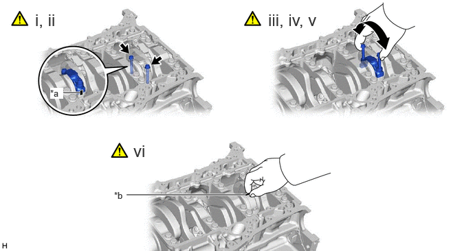
| *a | Matchmarks | *b | Plastigage |
Check that the matchmarks on the connecting rod sub-assembly and connecting rod cap are aligned.
- HINT:
-
The matchmarks on the connecting rod sub-assembly and connecting rod cap are guides for correct reassembly.
Remove the 2 connecting rod cap bolts.
Using the 2 removed connecting rod cap bolts, remove the connecting rod cap and lower bearing by wiggling the connecting rod cap right and left.
- HINT:
-
Keep the lower bearing inserted to the connecting rod cap.
Clean the crank pin and bearing.
Check the crank pin and bearing for pitting and scratches.
Lay a strip of Plastigage on the crank pin.
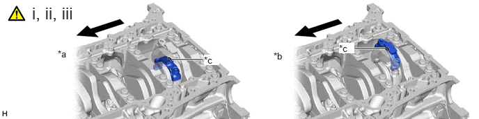
| *a | for Bank 1 (Piston RH) | *b | for Bank 2 (Piston LH) |
| *c | Piston Matchmark (Protrusion) | - | - |

|
Engine Front | - | - |
Check that the piston matchmark (protrusion) of the connecting rod cap is facing forward.
- NOTICE:
-
·
Take care as the piston matchmark (protrusion) on the piston RH connecting rod is reversed for the piston LH.
·The matchmarks on the connecting rod sub-assembly and connecting rod cap are guides for correct reassembly.
Install the connecting rod cap.
Click hereEngine / Hybrid System>V35A-FTS (ENGINE MECHANICAL)>CYLINDER BLOCK>REASSEMBLY
- NOTICE:
-
Do not turn the crankshaft.
Remove the 2 bolts and connecting rod cap.
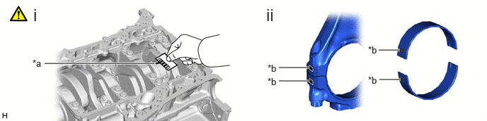
| *a | Plastigage | *b | Number Mark |
Measure the Plastigage at its widest point.
- Standard oil clearance:
-
0.047 to 0.075 mm (0.00185 to 0.00295 in.)
- Maximum oil clearance:
-
0.080 mm (0.00315 in.)
If the oil clearance is more than the maximum, replace the connecting rod bearings. If necessary, inspect the crankshaft.
If replacing a bearing, replace it with one that has the same number as its respective connecting rod cap. Each bearing standard thickness is indicated by a number (1, 2, 3 or 4) marked on its surface.
- Standard Connecting Rod Diameter:
-
Mark Specified Condition 1 59.600 to 59.606 mm (2.34645 to 2.34669 in.) 2 59.607 to 59.612 mm (2.34673 to 2.34692 in.) 3 59.613 to 59.618 mm (2.34696 to 2.34716 in.) 4 59.619 to 59.624 mm (2.34720 to 2.34740 in.)
- Standard Connecting Rod Bearing Center Wall Thickness:
-
Mark Specified Condition 1 1.482 to 1.485 mm (0.05835 to 0.05846 in.) 2 1.486 to 1.488 mm (0.05850 to 0.05858 in.) 3 1.489 to 1.491 mm (0.05862 to 0.05870 in.) 4 1.492 to 1.494 mm (0.05874 to 0.05882 in.)
- Standard crankshaft pin diameter:
-
56.592 to 56.600 mm (2.22803 to 2.22834 in.)
- NOTICE:
-
Completely remove the Plastigage after the measurement.
3.REMOVE PISTON SUB-ASSEMBLY WITH CONNECTING ROD
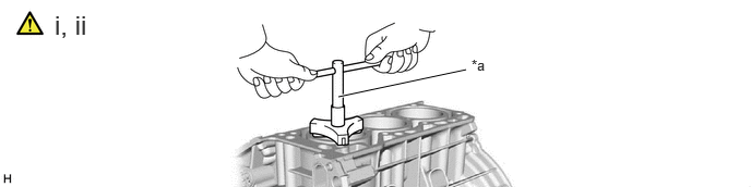
| *a | Ridge Reamer | - | - |
Using a ridge reamer, remove all the carbon from the top of the cylinder.
Push the piston, connecting rod sub-assembly and upper bearing through the top of the cylinder block sub-assembly.
- HINT:
-
·
Keep the bearing, connecting rod and cap together.
·Arrange the piston and connecting rod assemblies in the correct order.
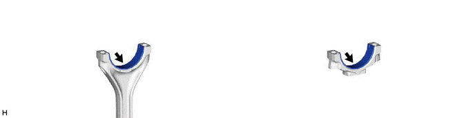
13041 4.REMOVE CONNECTING ROD BEARING
13411 5.REMOVE CRANKSHAFT
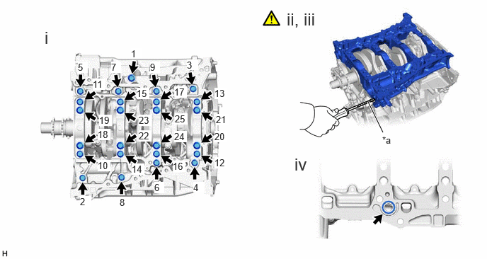
| *a | Protective Tape | - | - |
Uniformly loosen the 16 crankshaft bearing cap set bolts and the 9 crankshaft bearing cap bolts in several steps and in the sequence shown in the illustration.
Using a screwdriver, pry out the crankshaft bearing cap sub-assembly.
- NOTICE:
-
·
Push up on the cap slowly and evenly, alternating from the right and left side so that the crankshaft bearing cap sub-assembly can be removed.
·Be careful not to damage the joint surfaces of the cylinder block and the crankshaft bearing cap sub-assembly.
- HINT:
-
Tape the screwdriver tip before use.
Remove the crankshaft from the cylinder block sub-assembly.
Remove the gasket from the crankshaft bearing cap sub-assembly.
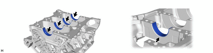
11711 6.REMOVE CRANKSHAFT BEARING
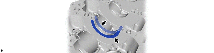
11011 7.REMOVE CRANKSHAFT THRUST WASHER SET
13011 8.REMOVE PISTON RING SET
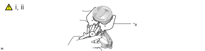
| *a | Piston Ring Expander | - | - |
Using a piston ring expander, remove the 2 compression rings.
Remove the oil ring expander and 2 side rails by hand.
- HINT:
-
Arrange the removed parts in the correct order.
9.REMOVE PISTON SUB-ASSEMBLY WITH PIN
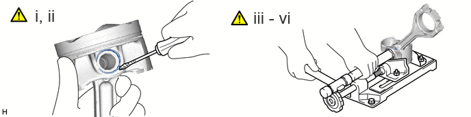
Using a screwdriver, pry off the piston pin hole snap rings from the piston.
- HINT:
-
Tape the screwdriver tip before use.
Gradually heat the piston to approximately 80°C (176°F).
Using a brass bar and a plastic-faced hammer, lightly tap out the piston pin and remove the connecting rod sub-assembly.
- HINT:
-
The piston and piston pin are a matched set.
Using a gasket scraper, remove the carbon from the piston top.
Using a groove cleaning tool or broken ring, clean the piston ring grooves.
Using solvent and a brush, thoroughly clean the piston.
- NOTICE:
-
Do not use a wire brush.
15708 10.REMOVE NO. 1 OIL NOZZLE SUB-ASSEMBLY
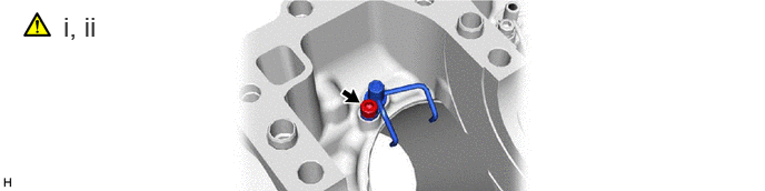
Using a 5 mm hexagon wrench, remove the 6 bolts and No. 1 oil nozzle sub-assemblies.
Check the 6 No. 1 oil nozzle sub-assemblies for damage or clogging.
If necessary, replace the No. 1 oil nozzle sub-assembly.
11432R 11.REMOVE CYLINDER BLOCK PLUG WITH HEAD STRAIGHT SCREW
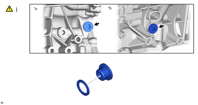
| *a | for Bank 1 | *b | for Bank 2 |
Using a 10 mm hexagon socket, remove the cylinder block plug with head straight screw and gasket from the cylinder block sub-assembly.
12.REMOVE RING PIN
|
|
|
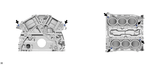
13.REMOVE STRAIGHT PIN
|
|
|