V35A-FTS LUBRICATION OIL PAN AND OIL LEVEL SENSOR REMOVAL
CAUTION / NOTICE / HINT
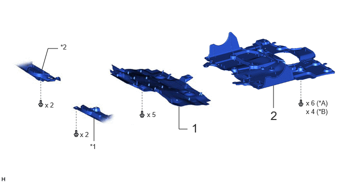
| Procedure | Part Name Code |

|

|

|
|
|---|---|---|---|---|---|
| 1 | NO. 1 ENGINE UNDER COVER ASSEMBLY | 51410 | - | - | - |
| 2 | NO. 2 ENGINE UNDER COVER ASSEMBLY | 51420 | - | - | - |
| *A | w/ Cover | *B | w/o Cover |
| *1 | ENGINE SIDE COVER SUB-ASSEMBLY LH | *2 | ENGINE SIDE COVER SUB-ASSEMBLY RH |
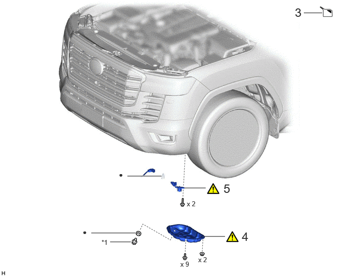
| Procedure | Part Name Code |
|
|
|
|
|---|---|---|---|---|---|
| 3 | DRAIN ENGINE OIL | - | - | ( ) |
- |
| 4 | NO. 2 OIL PAN SUB-ASSEMBLY | 12102A | () |
- | - |
| 5 | ENGINE OIL LEVEL SENSOR | 89491 | () |
- | - |
| *1 | OIL PAN DRAIN PLUG | - | - |
| ● | Non-reusable part | - | - |
CAUTION / NOTICE / HINT
- CAUTION:
-
To prevent burns, do not remove the engine oil level sensor while the engine is hot.
- NOTICE:
-
This procedure includes the removal of small-head bolts. Refer to Small-Head Bolts of Basic Repair Hint to identify the small-head bolts.
-
Click hereGeneral>INTRODUCTION>REPAIR INSTRUCTION>PRECAUTION
PROCEDURE

 51410 1.REMOVE NO. 1 ENGINE UNDER COVER ASSEMBLY
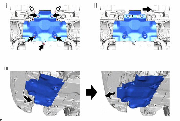

|
Bolt A |

|
Bolt B |

|
Remove in this Direction | - | - |
Remove the 5 bolts (A) and 4 bolts (B).
Move the side of the No. 1 engine under cover assembly facing the front of the vehicle toward the LH side and detach the temporary holding guide.
Remove the No. 1 engine under cover assembly facing the front of the vehicle while pulling the engine side cover sub-assembly RH and engine side cover sub-assembly LH, and then remove the No. 1 engine under cover assembly while detaching the 2 temporary holding guides facing the rear of the vehicle as shown in the illustration.
51420 2.REMOVE NO. 2 ENGINE UNDER COVER ASSEMBLY
3.DRAIN ENGINE OIL
12102A 4.REMOVE NO. 2 OIL PAN SUB-ASSEMBLY
|
|
Click here() |
89491 5.REMOVE ENGINE OIL LEVEL SENSOR
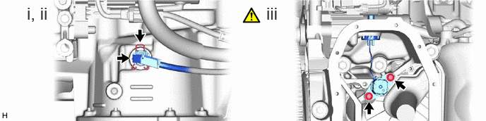
Disconnect the engine oil level sensor connector.
Remove the clip from the engine oil level sensor.
Using an 8 mm socket wrench, remove the 2 bolts and engine oil level sensor.