MAINTENANCE V35A-FTS DRIVE BELT REMOVAL
CAUTION / NOTICE / HINT
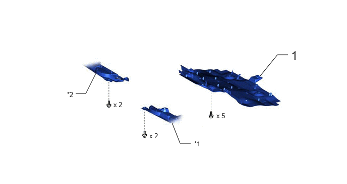
| Procedure | Part Name Code |

|

|

|
|
|---|---|---|---|---|---|
| 1 | NO. 1 ENGINE UNDER COVER ASSEMBLY | 51410 | - | - | - |
| *1 | ENGINE SIDE COVER SUB-ASSEMBLY LH | *2 | ENGINE SIDE COVER SUB-ASSEMBLY RH |
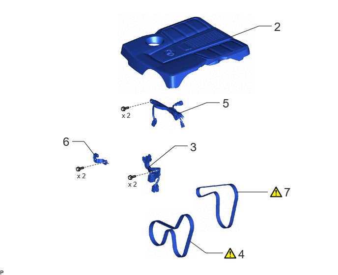
| Procedure | Part Name Code |
|
|
|
|
|---|---|---|---|---|---|
| 2 | V-BANK COVER SUB-ASSEMBLY | 11209 | - | - | - |
| 3 | COOLING FAN WIRE | 16364A | - | - | - |
| 4 | NO. 1 V BELT (COOLER COMPRESSOR TO CRANKSHAFT PULLEY) | 88310A | ( ) |
- | - |
| 5 | ENGINE WIRE | 82121 | - | - | - |
| 6 | NO. 1 AIR TUBE SUPPORT | 17368G | - | - | - |
| 7 | FAN AND GENERATOR V BELT | 16361A | () |
- | - |
PROCEDURE

 51410 1.REMOVE NO. 1 ENGINE UNDER COVER ASSEMBLY
11209 2.REMOVE V-BANK COVER SUB-ASSEMBLY
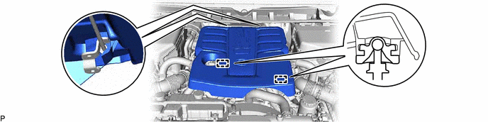
16364A 3.REMOVE COOLING FAN WIRE
88310A 4.REMOVE NO. 1 V BELT (COOLER COMPRESSOR TO CRANKSHAFT PULLEY)
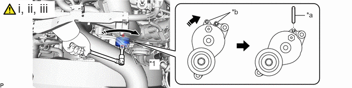
| *1 | No. 2 V-ribbed Belt Tensioner Assembly | - | - |
| *a | 5 mm Hexagon Wrench | *b | Hole |

|
Turn in this Direction | - | - |
Release the No. 1 V belt (cooler compressor to crankshaft pulley) tension by turning the No. 2 V-ribbed belt tensioner assembly clockwise and remove the No. 1 V belt (cooler compressor to crankshaft pulley) from the No. 2 V-ribbed belt tensioner assembly.
Rotate the No. 2 V-ribbed belt tensioner assembly clockwise to align the holes and then insert a 5 mm hexagon wrench to secure the No. 2 V-ribbed belt tensioner assembly in place.
Remove the No. 1 V belt (cooler compressor to crankshaft pulley).
82121 5.DISCONNECT ENGINE WIRE

17368G 6.REMOVE NO. 1 AIR TUBE SUPPORT

16361A 7.REMOVE FAN AND GENERATOR V BELT
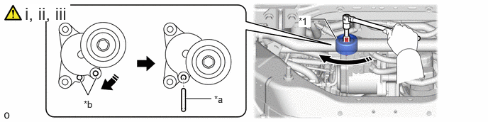
| *1 | V-ribbed Belt Tensioner Sub-assembly | - | - |
| *a | 5 mm Hexagon Wrench | *b | Hole |
|
|
Turn in this Direction | - | - |
Release the fan and generator V belt tension by turning the V-ribbed belt tensioner sub-assembly clockwise and remove the fan and generator V belt from the V-ribbed belt tensioner sub-assembly.
Rotate the V-ribbed belt tensioner sub-assembly clockwise to align the holes and then insert a 5 mm hexagon wrench to secure the V-ribbed belt tensioner sub-assembly in place.
Remove the fan and generator V belt.