Home › Vehicle Exterior › WIPER / WASHER › WIPER AND WASHER SYSTEM
RM38G0E _59 Vehicle Exterior _100456 WIPER / WASHER _0467584 WIPER AND WASHER SYSTEM J

WIPER / WASHER  WIPER AND WASHER SYSTEM  Washer Nozzle Heater Circuit  


DESCRIPTION

The front washer nozzle and hose assembly controls the main body ECU and operates the front washer nozzle and hose assembly according to the ambient temperature.

WIRING DIAGRAM
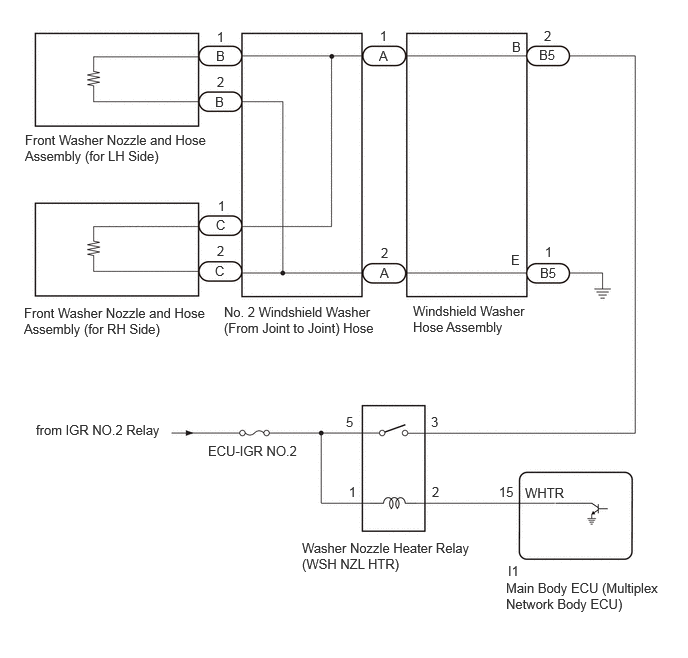
E465989E01
0.375,4.396 1.719,4.625 1.344,0.229 10 false from IGR NO.2 Relay 2.167,4.615 3.177,4.823 1.01,0.208 10 false ECU-IGR NO.2 3.146,5.625 4.969,6.135 1.823,0.51 10 false Washer Nozzle Heater Relay (WSH NZL HTR) 5.198,5.042 6.01,5.406 0.813,0.365 10 false 15 5.292,5.865 5.75,6.063 0.458,0.198 10 false I1 5.271,6.042 6.927,6.542 1.656,0.5 10 false Main Body ECU (Multiplex Network Body ECU) 5.469,5.052 6.083,5.25 0.615,0.198 10 false WHTR 4.5,5.042 4.656,5.24 0.156,0.198 10 false 2 3.635,5.042 3.792,5.24 0.156,0.198 10 false 1 3.604,4.313 3.76,4.51 0.156,0.198 10 false 5 4.49,4.313 4.646,4.51 0.156,0.198 10 false 3 2.333,3.167 3.958,3.573 1.625,0.406 10 false No. 2 Windshield Washer (From Joint to Joint) Hose 5.333,0.406 5.49,0.604 0.156,0.198 10 false B 5.323,2.625 5.479,2.823 0.156,0.198 10 false E 5.667,0.292 5.823,0.49 0.156,0.198 10 false 2 3.958,0.292 4.115,0.49 0.156,0.198 10 false 1 5.677,2.542 5.833,2.74 0.156,0.198 10 false 1 3.969,2.552 4.125,2.75 0.156,0.198 10 false 2 0.26,1.375 2.177,1.719 1.917,0.344 10 false Front Washer Nozzle and Hose Assembly (for LH Side) 0.25,3.177 2.188,3.573 1.938,0.396 10 false Front Washer Nozzle and Hose Assembly (for RH Side) 2.25,0.5 2.406,0.698 0.156,0.198 10 false B 2.25,2.26 2.406,2.458 0.156,0.198 10 false C 2.24,0.979 2.396,1.177 0.156,0.198 10 false B 2.24,2.74 2.396,2.938 0.156,0.198 10 false C 3.948,0.5 4.104,0.698 0.156,0.198 10 false A 3.958,2.76 4.115,2.958 0.156,0.198 10 false A 5.615,0.49 5.833,0.698 0.219,0.208 10 false B5 5.625,2.76 5.833,2.958 0.208,0.198 10 false B5 4.302,3.156 5.521,3.604 1.219,0.448 10 false Windshield Washer Hose Assembly 2.26,0.771 2.417,0.969 0.156,0.198 10 false 2 2.26,0.302 2.417,0.5 0.156,0.198 10 false 1 2.26,2.531 2.417,2.729 0.156,0.198 10 false 2 2.271,2.063 2.427,2.26 0.156,0.198 10 false 1

CAUTION / NOTICE / HINT

NOTICE:
·

Inspect the fuses for circuits related to this system before performing the following procedure.

·

Before replacing the main body ECU (multiplex network body ECU), refer to the Service Bulletin.


PROCEDURE

1.PERFORM ACTIVE TEST USING GTS (WASHER NOZZLE HEATER)
a.

Disconnect the B5 windshield washer hose assembly connector.


b.

Perform the Active Test according to the display on the GTS.

Body Electrical > Main Body > Active Test
Tester Display Measurement Item Control Range Diagnostic Note
Washer Nozzle Heater Washer nozzle heater operation OFF or ON -
Body Electrical > Main Body > Active Test
Tester Display
Washer Nozzle Heater
50004 449 80

c.
C443792C02
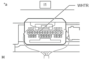
1.458,0.042 1.854,0.302 0.396,0.26 1.438,1.156 2.531,0.198 2.531,0.198 2.75,0.198 true 0.135,0.073 0.448,0.271 0.313,0.198 10 false *a 1.594,0.083 2.052,0.281 0.458,0.198 10 false I1 2.833,0.115 3.333,0.333 0.5,0.219 10 false WHTR
*a Component with harness connected
Main Body ECU (Multiplex Network Body ECU)


Measure the voltage according to the value(s) in the table below.

Standard Voltage:
Tester Connection Switch Condition Specified Condition

Click Location & Routing(I1)Location & Routing

Click Connector(I1)Instrument Panel>Instrument Panel Wire / Mobile Wireless Charger Cord / No. 1 Navigation Wire / No. 2 Instrument Panel Wire / No. 5 Instrument Panel Wire / Telephone Computer Wire>Main Body ECU

I1-15 (WHTR) - Body ground Ignition switch ON, Active Test is not performed 11 to 14 V
Ignition switch ON, Active Test is performed Below 1 V


Result:
Proceed to
OK
NG


OK

2.CHECK HARNESS AND CONNECTOR (WINDSHIELD WASHER HOSE ASSEMBLY - BODY GROUND)

NG

6.INSPECT WASHER NOZZLE HEATER RELAY (WSH NZL HTR)
2.CHECK HARNESS AND CONNECTOR (WINDSHIELD WASHER HOSE ASSEMBLY - BODY GROUND)
a.

Disconnect the B5 windshield washer hose assembly connector.


b.

Measure the resistance according to the value(s) in the table below.

Standard Resistance:
Tester Connection Condition Specified Condition

Click Location & Routing(B5)Location & Routing

Click Connector(B5)Engine Compartment>Engine Room Main Wire / Lamp Wire / No. 2 Engine Room Wire / No. 2 Lamp Wire / No. 3 Engine Room Wire / No. 6 Engine Room Wire / Washer Wiring Assembly>Front Washer Nozzle & Hose Assembly

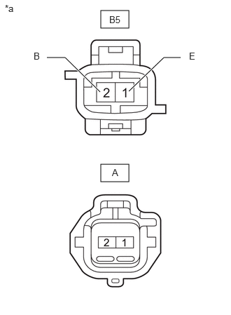
B5-1 (E) - Body ground Always Below 1 Ω


Result:
Proceed to
OK
NG


OK

3.INSPECT FRONT WASHER NOZZLE AND HOSE ASSEMBLY

NG

REPAIR OR REPLACE HARNESS OR CONNECTOR

3.INSPECT FRONT WASHER NOZZLE AND HOSE ASSEMBLY

OK

4.INSPECT NO. 2 WINDSHIELD WASHER (FROM JOINT TO JOINT) HOSE

NG

REPLACE FRONT WASHER NOZZLE AND HOSE ASSEMBLY

4.INSPECT NO. 2 WINDSHIELD WASHER (FROM JOINT TO JOINT) HOSE
a.

Remove the No. 2 windshield washer (from joint to joint) hose.
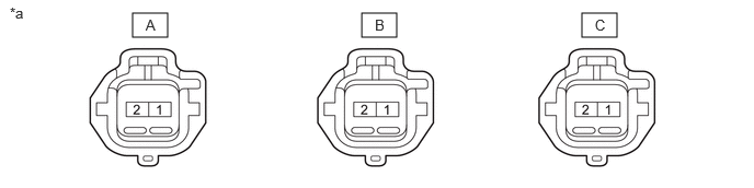
E466200C01
1.26,0.125 1.594,0.354 0.333,0.229 3.438,0.125 3.771,0.354 0.333,0.229 5.531,0.125 5.865,0.354 0.333,0.229 1.385,0.156 1.542,0.354 0.156,0.198 10 false A 3.563,0.156 3.719,0.354 0.156,0.198 10 false B 5.656,0.156 5.813,0.354 0.156,0.198 10 false C 0.094,0.042 0.406,0.198 0.313,0.156 10 false *a
*a Component without harness connected
(No. 2 Windshield Washer [From Joint to Joint] Hose)
- -


b.

Measure the resistance according to the value(s) in the table below.

Standard Resistance:
Tester Connection Condition Specified Condition
A-1 - B-1 Always Below 1 Ω
A-1 - C-1 Always Below 1 Ω
A-2 - B-2 Always Below 1 Ω
A-2 - C-2 Always Below 1 Ω


Result:
Proceed to
OK
NG


OK

5.INSPECT WINDSHIELD WASHER HOSE ASSEMBLY

NG

REPLACE NO. 2 WINDSHIELD WASHER (FROM JOINT TO JOINT) HOSE

5.INSPECT WINDSHIELD WASHER HOSE ASSEMBLY
a.
E466201C01
1.5,0.156 1.917,0.417 0.417,0.26 1.5,2.438 1.917,2.698 0.417,0.26 1.917,1.354 2.438,0.854 2.438,0.854 2.688,0.854 true 1.49,1.365 0.969,0.854 0.969,0.854 0.698,0.854 true 0.073,0.042 0.385,0.198 0.313,0.156 10 false *a 1.625,0.208 1.938,0.406 0.313,0.198 10 false B5 1.667,2.479 1.823,2.677 0.156,0.198 10 false A 2.813,0.75 2.969,0.948 0.156,0.198 10 false E 0.5,0.75 0.656,0.948 0.156,0.198 10 false B
*a Component without harness connected
(Windshield Washer Hose Assembly)


Remove the windshield washer hose assembly.


b.

Measure the resistance according to the value(s) in the table below.

Standard Resistance:
Tester Connection Condition Specified Condition

Click Location & Routing(B5)Location & Routing

Click Connector(B5)Engine Compartment>Engine Room Main Wire / Lamp Wire / No. 2 Engine Room Wire / No. 2 Lamp Wire / No. 3 Engine Room Wire / No. 6 Engine Room Wire / Washer Wiring Assembly>Front Washer Nozzle & Hose Assembly

B5-2 (B) - A-1 Always Below 1 Ω
B5-1 (E) - A-2 Always Below 1 Ω


Result:
Proceed to
OK
NG


OK

PROCEED TO NEXT SUSPECTED AREA SHOWN IN PROBLEM SYMPTOMS TABLE

NG

REPLACE WINDSHIELD WASHER HOSE ASSEMBLY

6.INSPECT WASHER NOZZLE HEATER RELAY (WSH NZL HTR)

OK

7.CHECK HARNESS AND CONNECTOR (WASHER NOZZLE HEATER RELAY [WSH NZL HTR] - BATTERY)

NG

REPLACE WASHER NOZZLE HEATER RELAY (WSH NZL HTR)

7.CHECK HARNESS AND CONNECTOR (WASHER NOZZLE HEATER RELAY [WSH NZL HTR] - BATTERY)
a.
B472073C12
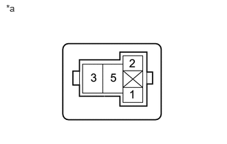
0.094,0.042 0.406,0.198 0.313,0.156 10 false *a
*a Front view of wire harness connector
(to Washer Nozzle Heater Relay [WSH NZL HTR])


Remove the washer nozzle heater relay (WSH NZL HTR) from the No. 1 engine room relay block assembly.


b.

Measure the voltage according to the value(s) in the table below.

Standard Voltage:
Tester Connection Switch Condition Specified Condition
Washer nozzle heater relay (WSH NZL HTR) terminal 5 - Body ground Ignition switch ON 11 to 14 V
Washer nozzle heater relay (WSH NZL HTR) terminal 1 - Body ground Ignition switch ON 11 to 14 V


Result:
Proceed to
OK
NG


OK

8.CHECK HARNESS AND CONNECTOR (WASHER NOZZLE HEATER RELAY [WSH NZL HTR] - MAIN BODY ECU [MULTIPLEX NETWORK BODY ECU])

NG

REPAIR OR REPLACE HARNESS OR CONNECTOR

8.CHECK HARNESS AND CONNECTOR (WASHER NOZZLE HEATER RELAY [WSH NZL HTR] - MAIN BODY ECU [MULTIPLEX NETWORK BODY ECU])
a.

Remove the washer nozzle heater relay (WSH NZL HTR) from the No. 1 engine room relay block assembly.


b.

Disconnect the I1 main body ECU (multiplex network body ECU) connector.


c.

Measure the resistance according to the value(s) in the table below.

Standard Resistance:
Tester Connection Condition Specified Condition

Click Location & Routing(I1)Location & Routing

Click Connector(I1)Instrument Panel>Instrument Panel Wire / Mobile Wireless Charger Cord / No. 1 Navigation Wire / No. 2 Instrument Panel Wire / No. 5 Instrument Panel Wire / Telephone Computer Wire>Main Body ECU

Washer nozzle heater relay (WSH NZL HTR) terminal 2 - I1-15 (WHTR) Always Below 1 Ω


Result:
Proceed to
OK
NG


OK

9.CHECK HARNESS AND CONNECTOR (WASHER NOZZLE HEATER RELAY [WSH NZL HTR] - WINDSHIELD WASHER HOSE ASSEMBLY)

NG

REPAIR OR REPLACE HARNESS OR CONNECTOR

9.CHECK HARNESS AND CONNECTOR (WASHER NOZZLE HEATER RELAY [WSH NZL HTR] - WINDSHIELD WASHER HOSE ASSEMBLY)
a.

Remove the washer nozzle heater relay (WSH NZL HTR) from the No. 1 engine room relay block assembly.


b.

Disconnect the B5 windshield washer hose assembly connector.


c.

Measure the resistance according to the value(s) in the table below.

Standard Resistance:
Tester Connection Condition Specified Condition

Click Location & Routing(B5)Location & Routing

Click Connector(B5)Engine Compartment>Engine Room Main Wire / Lamp Wire / No. 2 Engine Room Wire / No. 2 Lamp Wire / No. 3 Engine Room Wire / No. 6 Engine Room Wire / Washer Wiring Assembly>Front Washer Nozzle & Hose Assembly

Washer nozzle heater relay (WSH NZL HTR) terminal 3 - B5-2 (B) Always Below 1 Ω
Washer nozzle heater relay (WSH NZL HTR) terminal 3 or B5-2 (B) - Body ground Always 10 kΩ or higher


Result:
Proceed to
OK
NG


OK

NG

REPAIR OR REPLACE HARNESS OR CONNECTOR