PARK ASSIST / MONITORING CLEARANCE WARNING ECU INSTALLATION
CAUTION / NOTICE / HINT
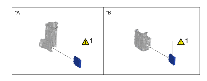
| Procedure | Part Name Code |

|

|

|
|
|---|---|---|---|---|---|
| 1 | CLEARANCE WARNING ECU ASSEMBLY | 89340A | ( ) |
- | - |
| *A | for LHD | *B | for RHD |
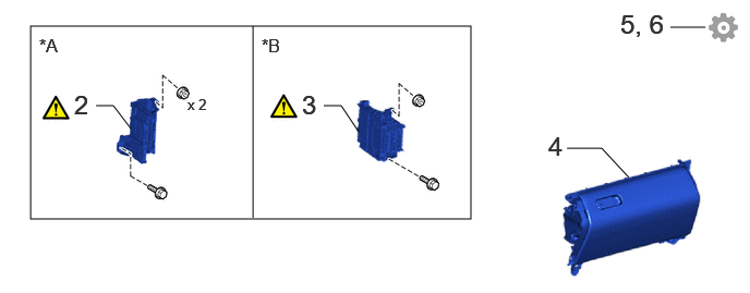
| Procedure | Part Name Code |
|
|
|
|
|---|---|---|---|---|---|
| 2 | ECU INTEGRATION BOX RH | 82877 | () |
- | - |
| 3 | ECU INTEGRATION BOX LH | 82878 | () |
- | - |
| 4 | LOWER NO. 2 INSTRUMENT PANEL ASSEMBLY | 55320 | - | - | - |
| 5 | UPDATE ECU SECURITY KEY | - | - | - | () |
| 6 | PERFORM CALIBRATION | - | - | - | () |
| *A | for LHD | *B | for RHD |
- NOTICE:
-
After performing the update ECU security key procedure, make sure to perform the initialization procedure for when the cable has been disconnected and reconnected to the negative (-) auxiliary battery terminal.
- HINT:
-
A bolt without a torque specification is shown in the standard bolt chart.
-
Click hereGeneral>SPECIFICATIONS>STANDARD BOLT>SPECIFIED TORQUE FOR STANDARD BOLTS
PROCEDURE

 89340A 1.INSTALL CLEARANCE WARNING ECU ASSEMBLY
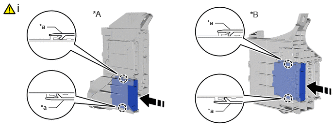
| *A | for LHD | *B | for RHD |
| *a | Retainer | - | - |

|
Install in this Direction | - | - |
Attach the claw and install the clearance warning ECU.
- NOTICE:
-
Be sure that the ECU integration box RH (LH) is over the retainer of the clearance warning ECU as shown in the illustration.
82877 2.INSTALL ECU INTEGRATION BOX RH (for LHD)
|
|
Click here() |
82878 3.INSTALL ECU INTEGRATION BOX LH (for RHD)
|
|
Click here() |
55320 4.INSTALL LOWER NO. 2 INSTRUMENT PANEL ASSEMBLY
5. UPDATE ECU SECURITY KEY
6. PERFORM CALIBRATION