HEATING / AIR CONDITIONING AIR CONDITIONING SYSTEM Air Vent Temperature does not Change and Right Vent is Different from Left and Vice Versa (Same Left/Right Temperature Setting)
DESCRIPTION
If the temperature of the air that blows from the left and right front registers differs even though the same temperature is set for both sides, the following factors may be the cause.
| Symptom | Factor |
|---|---|
| Temperature of outlet air is cooler on left or right side (When same temperature set for both sides) |
·
Cooler compressor assembly malfunction
·
Quantity of refrigerant gas lack
·
A/M servo motor malfunction
·
Damper and link operation (jamming)
·
Automatic light control sensor malfunction |
| Temperature of outlet air is warmer on left or right side (When same temperature set for both sides) |
·
A/M servo motor malfunction
·
Damper and link operation (jamming)
·
Blockage in heater radiator unit assembly |
WIRING DIAGRAM
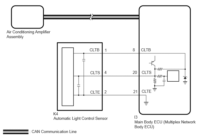
CAUTION / NOTICE / HINT
- NOTICE:
-
·
If DTC B124400 is output, perform troubleshooting for that DTC first.
Click hereVehicle Exterior>LIGHTING (EXT)>LIGHTING SYSTEM (w/ Headlight ECU)>B124400
·The air conditioning system uses the CAN communication system. Inspect the communication functions by following How to Proceed with Troubleshooting. Troubleshoot the air conditioning system after confirming that the communication systems are functioning properly.
Click herePower Source / Network>NETWORKING>CAN COMMUNICATION SYSTEM>HOW TO PROCEED WITH TROUBLESHOOTING
PROCEDURE
- Result:
-
Result Proceed to Malfunction occurs during cooling A Malfunction occurs during heating B
A
B
Prepare the vehicle according to the table below.
| Item | Condition |
|---|---|
| Vehicle Condition | Engine running |
| A/C Switch | On |
| Ambient Temperature*1 | 0 to 49°C (32 to 120°F) |
| Air Conditioning Air Inlet Temperature*2 | 25 to 35°C (77 to 95°F) |
| Set Temperature | MAX COLD |
| Recirculation/fresh Control Switch | Recirculation |
| Air Vent Damper Position | FACE |
| Blower Speed | HI |
- HINT:
-
*1: This inspection can be judged correctly only if the ambient temperature is within a range of 0 to 49°C (32 to 120°F). Therefore, postpone the test if the temperature is low.
-
*2: This inspection can be judged correctly only if the air inlet temperature is within a range of 25 to 35°C (77 to 95°F). Therefore, postpone the test if the temperature is out of range.
Using the GTS, check the amount of refrigerant.
- Body Electrical > Air Conditioner > Utility
-
Tester Display Refrigerant Gas Volume Check - 50005 450 4578
- NOTICE:
-
If the conditions for the inspection are not met, "Refrigerant incorrect" will be displayed on the GTS. Confirm the conditions of the inspection and perform the check again.
- HINT:
-
·
If the amount of refrigerant is insufficient, "Refrigerant shortage" is displayed on the GTS and the indicator light on the A/C switch turns off.
·When performing this inspection, a DTC will not be output even if "Refrigerant shortage" is displayed on the GTS.
- Result:
-
Result Amount of Refrigerant Refrigerant shortage Insufficient or leakage Refrigerant correct Correct Refrigerant incorrect Incorrect
- OK:
-
"Refrigerant correct" is displayed on the GTS.
- Result:
-
Proceed to OK NG
OK
NG
Perform the Active Test according to the display on the GTS.
- Body Electrical > Air Conditioner > Active Test
-
Tester Display Measurement Item Control Range Diagnostic Note Front Left Air Mix Damper Control Servo Motor No. 2 air conditioning radiator damper servo sub-assembly operation 128: Min
384: MaxOperates between 254 to 326 FL Air Mix Cool Damper Control Servo Motor No. 2 air conditioning radiator damper servo sub-assembly operation 128: Min
384: Maxfor Dual:Operates between 154 to 258
for 4 Zone:Operates between 254 to 358
Front Right Air Mix Damper Control Servo Motor No. 4 air conditioning radiator damper servo sub-assembly operation 128: Min
384: MaxOperates between 186 to 258 FR Air Mix Cool Damper Control Servo Motor No. 4 air conditioning radiator damper servo sub-assembly operation 128: Min
384: MaxOperates between 154 to 258 Fr Control RL Air Mix Damper Control Servo Motor No. 2 air conditioning radiator damper servo sub-assembly operation 128: Min
384: MaxOperates between 154 to 258 Fr Control RR Air Mix Damper Control Servo Motor No. 4 air conditioning radiator damper servo sub-assembly operation 128: Min
384: MaxOperates between 154 to 258 Rear Left Air Mix Damper Control Servo Motor Rear air mix damper servo sub-assembly operation 128: Min
384: MaxOperates between 254 to 299 pulses (w/ Rear Air Conditioning System) Rear Right Air Mix Damper Control Servo Motor No. 2 rear air mix damper servo sub-assembly operation 128: Min
384: MaxOperates between 254 to 299 pulses (w/ Rear Air Conditioning System)
- Body Electrical > Air Conditioner > Active Test
-
Tester Display Front Left Air Mix Damper Control Servo Motor - 50004 450 26 201
- Body Electrical > Air Conditioner > Active Test
-
Tester Display FL Air Mix Cool Damper Control Servo Motor - 50004 450 27
- Body Electrical > Air Conditioner > Active Test
-
Tester Display Front Right Air Mix Damper Control Servo Motor - 50004 450 28 205
- Body Electrical > Air Conditioner > Active Test
-
Tester Display FR Air Mix Cool Damper Control Servo Motor - 50004 450 29
- Body Electrical > Air Conditioner > Active Test
-
Tester Display Fr Control RL Air Mix Damper Control Servo Motor - 50004 450 36
- Body Electrical > Air Conditioner > Active Test
-
Tester Display Fr Control RR Air Mix Damper Control Servo Motor - 50004 450 37
- Body Electrical > Air Conditioner > Active Test
-
Tester Display Rear Left Air Mix Damper Control Servo Motor - 50004 450 42
- Body Electrical > Air Conditioner > Active Test
-
Tester Display Rear Right Air Mix Damper Control Servo Motor - 50004 450 43
- OK:
-
Damper servo motor is operated.
- Result:
-
Proceed to OK NG
OK
NG
Click hereVehicle Interior>HEATING / AIR CONDITIONING>AIR CONDITIONING SYSTEM>DIAGNOSTIC TROUBLE CODE CHART
Disconnect the K4 automatic light control sensor connector.
Disconnect the I3 main body ECU (multiplex network body ECU) connector.
Measure the resistance according to the value(s) in the table below.
- Standard Resistance:
-
Tester Connection Condition Specified Condition Click Location & Routing(K4,I3)Location & Routingewd_type=routing;type=c,c;code=K4,I3
Click Connector(K4)Instrument Panel>No. 3 Instrument Panel Wire>Automatic Light Control Sensorewd_type=component;type=c;code=K4;pinno=1,2,4
K4-1 (CLTB) - I3-8 (CLTB) Always Below 1 Ω K4-2 (CLTE) - I3-21 (CLTE) Always Below 1 Ω K4-4 (CLTS) - I3-20 (CLTS) Always Below 1 Ω K4-1 (CLTB) or I3-8 (CLTB) - Other terminals and body ground Always 10 kΩ or higher K4-2 (CLTE) or I3-21 (CLTE) - Other terminals and body ground Always 10 kΩ or higher K4-4 (CLTS) or I3-20 (CLTS) - Other terminals and body ground Always 10 kΩ or higher
- Result:
-
Proceed to OK NG
OK
NG
Click hereVehicle Exterior>LIGHTING (EXT)>AUTOMATIC LIGHT CONTROL SENSOR>ON-VEHICLE INSPECTION
- Result:
-
Proceed to OK NG
OK
Click hereVehicle Interior>HEATING / AIR CONDITIONING>REFRIGERANT (for HFC-134a(R134a))>ON-VEHICLE INSPECTION
NG
for 1GR-FE:Engine / Hybrid System>1GR-FE (COOLING)>COOLANT>REPLACEMENT
for V35A-FTS:Engine / Hybrid System>V35A-FTS (COOLING)>COOLANT>REPLACEMENT
- Result:
-
Proceed to NEXT
NEXT
Set the same temperature for the left and right sides and check that the air that blows from the left and right front registers is the same temperature.
- OK:
-
The air from the left and right front registers is the same temperature.
- Result:
-
Proceed to OK NG
OK
NG
Perform the Active Test according to the display on the GTS.
- Body Electrical > Air Conditioner > Active Test
-
Tester Display Measurement Item Control Range Diagnostic Note Front Left Air Mix Damper Control Servo Motor No. 2 air conditioning radiator damper servo sub-assembly operation 128: Min
384: MaxOperates between 254 to 326 FL Air Mix Cool Damper Control Servo Motor No. 2 air conditioning radiator damper servo sub-assembly operation 128: Min
384: Maxfor Dual:Operates between 154 to 258
for 4 Zone:Operates between 254 to 358
Front Right Air Mix Damper Control Servo Motor No. 4 air conditioning radiator damper servo sub-assembly operation 128: Min
384: MaxOperates between 186 to 258 FR Air Mix Cool Damper Control Servo Motor No. 4 air conditioning radiator damper servo sub-assembly operation 128: Min
384: MaxOperates between 154 to 258 Fr Control RL Air Mix Damper Control Servo Motor No. 2 air conditioning radiator damper servo sub-assembly operation 128: Min
384: MaxOperates between 154 to 258 Fr Control RR Air Mix Damper Control Servo Motor No. 4 air conditioning radiator damper servo sub-assembly operation 128: Min
384: MaxOperates between 154 to 258 Rear Left Air Mix Damper Control Servo Motor Rear air mix damper servo sub-assembly operation 128: Min
384: MaxOperates between 254 to 299 pulses (w/ Rear Air Conditioning System) Rear Right Air Mix Damper Control Servo Motor No. 2 rear air mix damper servo sub-assembly operation 128: Min
384: MaxOperates between 254 to 299 pulses (w/ Rear Air Conditioning System)
- Body Electrical > Air Conditioner > Active Test
-
Tester Display Front Left Air Mix Damper Control Servo Motor - 50004 450 26 201
- Body Electrical > Air Conditioner > Active Test
-
Tester Display FL Air Mix Cool Damper Control Servo Motor - 50004 450 27
- Body Electrical > Air Conditioner > Active Test
-
Tester Display Front Right Air Mix Damper Control Servo Motor - 50004 450 28 205
- Body Electrical > Air Conditioner > Active Test
-
Tester Display FR Air Mix Cool Damper Control Servo Motor - 50004 450 29
- Body Electrical > Air Conditioner > Active Test
-
Tester Display Fr Control RL Air Mix Damper Control Servo Motor - 50004 450 36
- Body Electrical > Air Conditioner > Active Test
-
Tester Display Fr Control RR Air Mix Damper Control Servo Motor - 50004 450 37
- Body Electrical > Air Conditioner > Active Test
-
Tester Display Rear Left Air Mix Damper Control Servo Motor - 50004 450 42
- Body Electrical > Air Conditioner > Active Test
-
Tester Display Rear Right Air Mix Damper Control Servo Motor - 50004 450 43
- OK:
-
Damper servo motor is operated.
- Result:
-
Proceed to OK NG
OK
NG
Click hereVehicle Interior>HEATING / AIR CONDITIONING>AIR CONDITIONING SYSTEM>DIAGNOSTIC TROUBLE CODE CHART