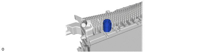
HEATING / AIR CONDITIONING FRONT AIR CONDITIONING UNIT(for RHD) DISASSEMBLY
CAUTION / NOTICE / HINT
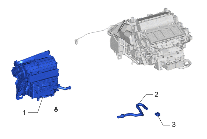
| Procedure | Part Name Code |

|

|

|
|
|---|---|---|---|---|---|
| 1 | BLOWER ASSEMBLY | 87130D | - | - | - |
| 2 | ASPIRATOR | 88897P | - | - | - |
| 3 | COOLER THERMISTOR (ROOM TEMPERATURE SENSOR) | 88625Q | - | - | - |
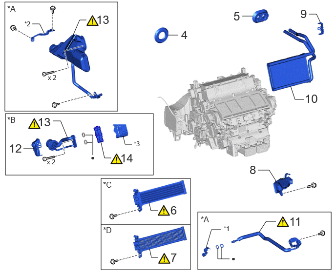
| Procedure | Part Name Code |
|
|
|
|
|---|---|---|---|---|---|
| 4 | GROMMET | 88898D | - | - | - |
| 5 | NO. 2 HEATER GROMMET | 87128B | - | - | - |
| 6 | QUICK HEATER ASSEMBLY | 87710G | ( ) |
- | - |
| 7 | HEATER COVER | 87114B | () |
- | - |
| 8 | NO. 2 AIR DUCT SUB-ASSEMBLY | 87201B | - | - | - |
| 9 | HEATER CLAMP | 87124B | - | - | - |
| 10 | HEATER RADIATOR UNIT SUB-ASSEMBLY | 87107A | - | - | - |
| 11 | AIR CONDITIONING TUBE ASSEMBLY | 88710A | () |
- | - |
| 12 | NO. 2 COOLER COVER | 88892N | - | - | - |
| 13 | AIR CONDITIONING TUBE ASSEMBLY | 88710B | () |
- | - |
| 14 | COOLER EXPANSION VALVE | 88515 | () |
- | - |
| *A | w/ Cool Box | *B | w/o Cool Box |
| *C | w/ PTC Heater | *D | w/o PTC Heater |
| *1 | PIPING CLAMP | *2 | BRACKET |
| *3 | NO. 1 COOLER COVER | - | - |
| ● | Non-reusable part | - | - |
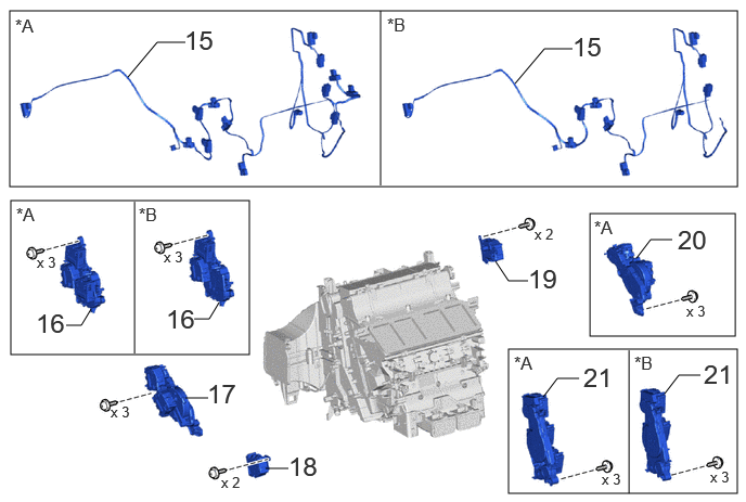
| Procedure | Part Name Code |
|
|
|
|
|---|---|---|---|---|---|
| 15 | AIR CONDITIONING HARNESS ASSEMBLY | 82210K | - | - | - |
| 16 | NO. 2 AIR CONDITIONING RADIATOR DAMPER SERVO SUB-ASSEMBLY | 87050D | - | - | - |
| 17 | NO. 1 AIR CONDITIONING RADIATOR DAMPER SERVO SUB-ASSEMBLY | 87050C | - | - | - |
| 18 | NO. 3 AIR CONDITIONING RADIATOR DAMPER SERVO SUB-ASSEMBLY | 87050E | - | - | - |
| 19 | NO. 5 AIR CONDITIONING RADIATOR DAMPER SERVO SUB-ASSEMBLY | 87050G | - | - | - |
| 20 | NO. 6 AIR CONDITIONING RADIATOR DAMPER SERVO SUB-ASSEMBLY | 87050H | - | - | - |
| 21 | NO. 4 AIR CONDITIONING RADIATOR DAMPER SERVO SUB-ASSEMBLY | 87050F | - | - | - |
| *A | for 4 Zone Type | *B | for Dual Type |
| Procedure | Part Name Code |
|
|
|
|
|---|---|---|---|---|---|
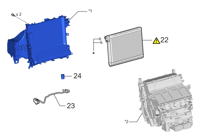
| 22 | NO. 1 COOLER EVAPORATOR SUB-ASSEMBLY | 88501 | () |
- | - |
| 23 | NO. 1 COOLER THERMISTOR | 88625 | - | - | - |
| 24 | NO. 1 COOLER UNIT DRAIN HOSE | 88539 | - | - | - |
| *1 | HEATER CASE (for Front Side) | *2 | HEATER CASE (for Rear Side) |
| ● | Non-reusable part | - | - |
PROCEDURE

 87130D 1.REMOVE BLOWER ASSEMBLY
88897P 2.REMOVE ASPIRATOR
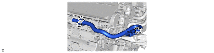
88625Q 3.REMOVE COOLER THERMISTOR (ROOM TEMPERATURE SENSOR)

88898D 4.REMOVE GROMMET
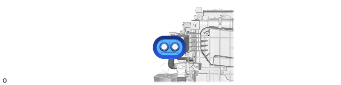
87128B 5.REMOVE NO. 2 HEATER GROMMET
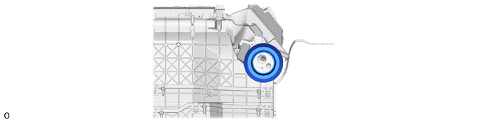
87710G 6.REMOVE QUICK HEATER ASSEMBLY (w/ PTC Heater)


|
Remove in this Direction | - | - |
Remove the screw.
Detach the claw and remove the quick heater assembly as shown in the illustration.
- NOTICE:
-
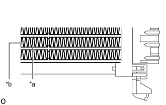 0.677,1.646 0.677,1 true 0.188,1.646 0.188,0.896 0.188,0.896 0.5,0.896 true 0.604,1.667 0.917,1.865 0.313,0.198 10 false *a 0.115,1.667 0.427,1.865 0.313,0.198 10 false *b
*a Element *b Fin
-
·
Do not hold the quick heater assembly by the element or fin. Also, do not damage the quick heater assembly.
·Foul odors may occur due to oil adhering to the quick heater assembly.
87114B 7.REMOVE HEATER COVER (w/o PTC Heater)
Use the same procedure as for the quick heater assembly.
87201B 8.REMOVE NO. 2 AIR DUCT SUB-ASSEMBLY
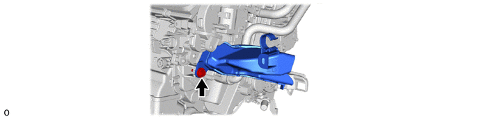
87124B 9.REMOVE HEATER CLAMP
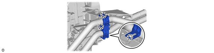
87107A 10.REMOVE HEATER RADIATOR UNIT SUB-ASSEMBLY
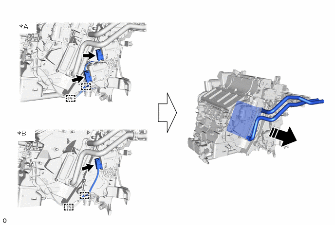
| *A | for 4 Zone Type | *B | for Dual Type |
|
|
Remove in this Direction | - | - |
88710A 11.REMOVE AIR CONDITIONING TUBE ASSEMBLY (w/ Cool Box)
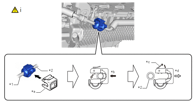
| *1 | Air Conditioning Tube Assembly | *2 | Air Conditioning Tube Assembly |
| *a | SST | *b | Push in |
| *c | Stopper | *d | Pull off |
Remove the piping clamp using the following procedure.
1. Install SST to the piping clamp as shown in the illustration.
- SST
-
09870-00025
2. Hold the air conditioning tube assembly and air conditioning tube assembly with each hand and push in SST with both thumbs.
- NOTICE:
-
Do not apply excessive force to the air conditioning tube assembly or air conditioning tube assembly as they may bend.
3. Raise the stopper of SST and remove SST and the piping clamp together from the air conditioning tube assembly and air conditioning tube assembly.
4. Remove the piping clamp from SST.
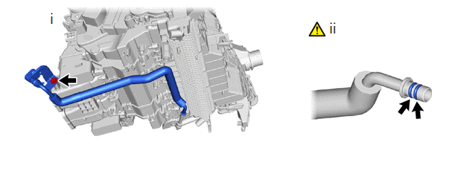
Remove the screw and air conditioning tube assembly.
Remove the 2 O-rings from the liquid tube.
- NOTICE:
-
Seal the openings of the disconnected parts using vinyl tape to prevent the entry of moisture and foreign matter.
88892N 12.REMOVE NO. 2 COOLER COVER (w/o Cool Box)

88710B 13.REMOVE AIR CONDITIONING TUBE ASSEMBLY
w/ Cool Box:
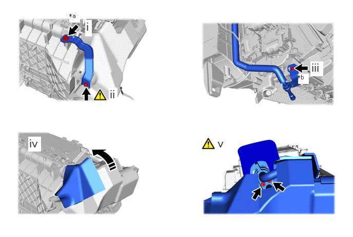
| *a | Screw (A) | *b | Screw (B) |
|
|
Remove in this Direction | - | - |
Remove the screw (A).
Using a 4 mm hexagon socket wrench, remove the hexagon bolt and bracket.
Remove the screw (B).
Remove a part of the packing as shown in the illustration.
Using a 4 mm hexagon socket wrench, remove the 2 hexagon bolts and air conditioning tube assembly.
w/o Cool Box:
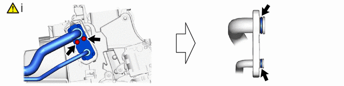
Remove the air conditioning tube assembly using the following procedure.
1. Using a 4 mm hexagon socket wrench, remove the 2 hexagon bolts and air conditioning tube assembly.
2. Remove the 2 O-rings from the air conditioning tube assembly.
- NOTICE:
-
Seal the openings of the disconnected parts using vinyl tape to prevent the entry of moisture and foreign matter.
88515 14.REMOVE COOLER EXPANSION VALVE (w/o Cool Box)
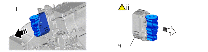
| *1 | No. 1 Cooler Cover | - | - |
|
|
Remove in this Direction (1) |

|
Remove in this Direction (2) |
Remove the cooler expansion valve together with the No. 1 cooler cover as shown in the illustration.
Remove the cooler expansion valve from the No. 1 cooler cover as shown in the illustration.
- NOTICE:
-
Seal the openings of the disconnected parts using vinyl tape to prevent the entry of moisture and foreign matter.
82210K 15.REMOVE AIR CONDITIONING HARNESS ASSEMBLY
for 4 Zone Type:
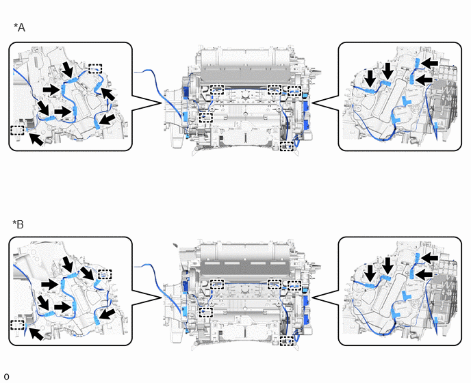
| *A | for Type A | *B | for Type B |
for Dual Type:
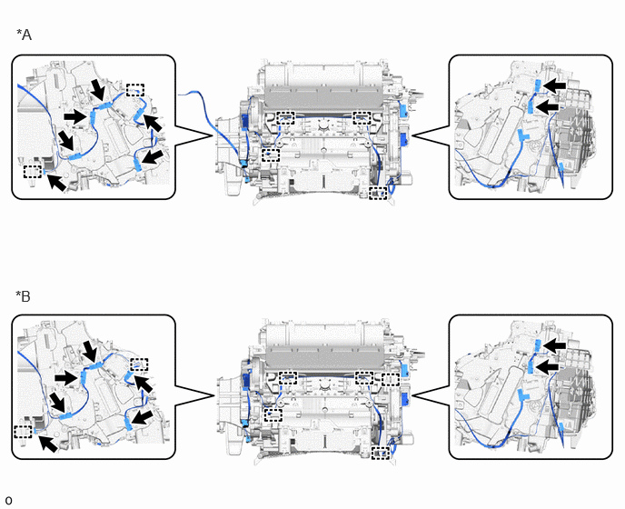
| *A | for Type A | *B | for Type B |
87050D 16.REMOVE NO. 2 AIR CONDITIONING RADIATOR DAMPER SERVO SUB-ASSEMBLY
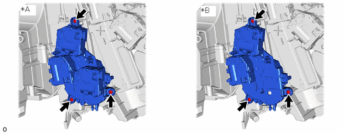
| *A | for 4 Zone Type | *B | for Dual Type |
87050C 17.REMOVE NO. 1 AIR CONDITIONING RADIATOR DAMPER SERVO SUB-ASSEMBLY
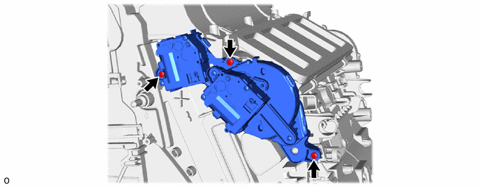
87050E 18.REMOVE NO. 3 AIR CONDITIONING RADIATOR DAMPER SERVO SUB-ASSEMBLY
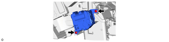
87050G 19.REMOVE NO. 5 AIR CONDITIONING RADIATOR DAMPER SERVO SUB-ASSEMBLY

87050H 20.REMOVE NO. 6 AIR CONDITIONING RADIATOR DAMPER SERVO SUB-ASSEMBLY (for 4 Zone Type)
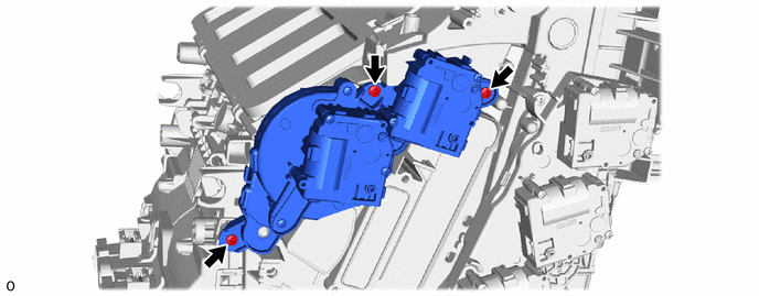
87050F 21.REMOVE NO. 4 AIR CONDITIONING RADIATOR DAMPER SERVO SUB-ASSEMBLY
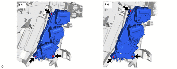
| *A | for 4 Zone Type | *B | for Dual Type |
88501 22.REMOVE NO. 1 COOLER EVAPORATOR SUB-ASSEMBLY
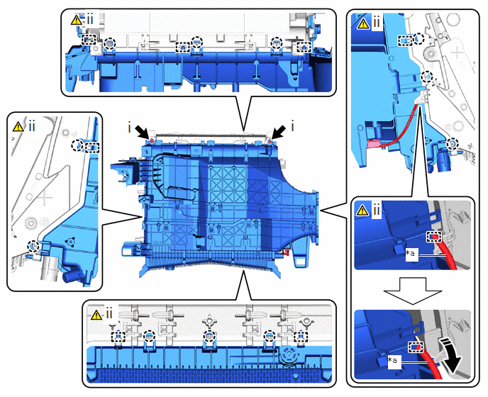
| *a | No. 1 Cooler Thermistor Lead Wire | - | - |
|
|
Detach Lead Wire from Guide | - | - |
Remove the 2 screws.
Detach the claw and guide and while detaching the lead wire of the No. 1 cooler thermistor from the guide, separate the heater case as shown in the illustration.
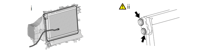
Remove the No. 1 cooler evaporator sub-assembly.
Remove the 2 O-rings from the No. 1 cooler evaporator sub-assembly.
- NOTICE:
-
Seal the openings of the disconnected parts using vinyl tape to prevent the entry of moisture and foreign matter.
88625 23.REMOVE NO. 1 COOLER THERMISTOR
88539 24.REMOVE NO. 1 COOLER UNIT DRAIN HOSE