INTERIOR PANELS / TRIM FRONT CONSOLE BOX(w/o Cool Box) REMOVAL
CAUTION / NOTICE / HINT
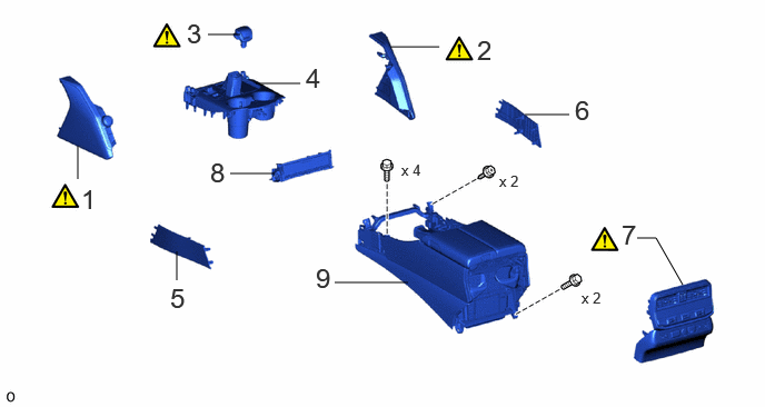
| Procedure | Part Name Code |

|

|

|
|
|---|---|---|---|---|---|
| 1 | INTEGRATION CONTROL AND PANEL SUB-ASSEMBLY | 84012 | ( ) |
- | - |
| 2 | LOWER NO. 2 INSTRUMENT PANEL PAD SUB-ASSEMBLY | 55403H | () |
- | - |
| 3 | SHIFT LEVER KNOB SUB-ASSEMBLY | 33504F | () |
- | - |
| 4 | UPPER CONSOLE PANEL ASSEMBLY | - | - | - | - |
| 5 | INNER NO. 1 INSTRUMENT PANEL BRACKET COVER LH | 55395C | - | - | - |
| 6 | INNER NO. 1 INSTRUMENT PANEL BRACKET COVER RH | 55394D | - | - | - |
| 7 | CONSOLE REAR END PANEL SUB-ASSEMBLY | 58903A | () |
- | - |
| 8 | CENTER INSTRUMENT CLUSTER FINISH PANEL SUB-ASSEMBLY | 55405B | - | - | - |
| 9 | REAR CONSOLE BOX SUB-ASSEMBLY | 58901A | - | - | - |
CAUTION / NOTICE / HINT
- HINT:
-
·
Use the same procedure for RHD and LHD vehicles.
·The procedure listed below is for LHD vehicles.
PROCEDURE

 84012 1.REMOVE INTEGRATION CONTROL AND PANEL SUB-ASSEMBLY
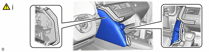
Apply the protective tape as shown in the illustration.
- NOTICE:
-
Use thick protective tape.
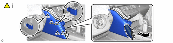

|
Place Hand Here |

|
Remove in this Direction |
Place your hand at the position shown in the illustration, and detach the clip.
- NOTICE:
-
Do not damage the integration control and panel sub-assembly or air conditioning panel assembly.
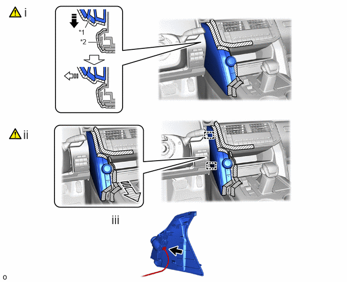
| *1 | Integration Control and Panel Sub-assembly | *2 | Air Conditioning Panel Assembly |
|
|
Remove in this Direction (1) |

|
Remove in this Direction (2) |

|
Remove in this Direction (3) | - | - |
Pull the integration control and panel sub-assembly to outward while avoiding contact with the air conditioning panel assembly as shown in the illustration.
- NOTICE:
-
Do not damage the integration control and panel sub-assembly or air conditioning panel assembly.
Detach the guide and remove the integration control and panel sub-assembly as shown in the illustration.
- NOTICE:
-
Do not damage the integration control and panel sub-assembly or vehicle interior.
Disconnect the connector.
55403H 2.REMOVE LOWER NO. 2 INSTRUMENT PANEL PAD SUB-ASSEMBLY
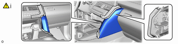
Apply the protective tape as shown in the illustration.
- NOTICE:
-
Use thick protective tape.
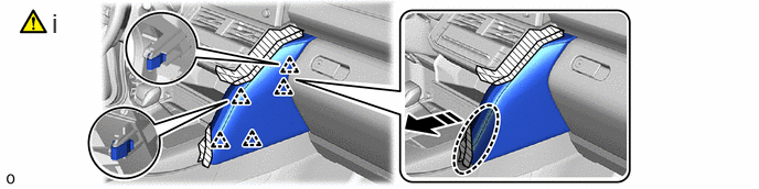
|
|
Place Hand Here |
|
Remove in this Direction |
Place your hand at the position shown in the illustration, and detach the clip.
- NOTICE:
-
Do not damage the lower No. 2 instrument panel pad sub-assembly or air conditioning panel assembly.
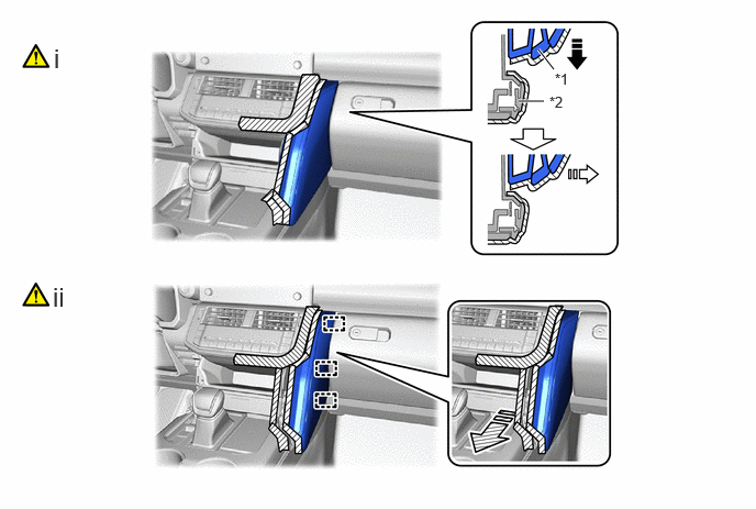
| *1 | Lower No. 2 Instrument Panel Pad Sub-assembly | *2 | Air Conditioning Panel Assembly |
|
|
Remove in this Direction (1) |
|
Remove in this Direction (2) |
|
|
Remove in this Direction (3) | - | - |
Pull the lower No. 2 instrument panel pad sub-assembly to outward while avoiding contact with the air conditioning panel assembly as shown in the illustration.
- NOTICE:
-
Do not damage the lower No. 2 instrument panel pad sub-assembly or air conditioning panel assembly.
Detach the guide and remove the lower No. 2 instrument panel pad sub-assembly as shown in the illustration.
- NOTICE:
-
Do not damage the lower No. 2 instrument panel pad sub-assembly or vehicle interior.
33504F 3.REMOVE SHIFT LEVER KNOB SUB-ASSEMBLY
|
|
·
for AC60F: Click here(
·
for AJA0F: Click here( |
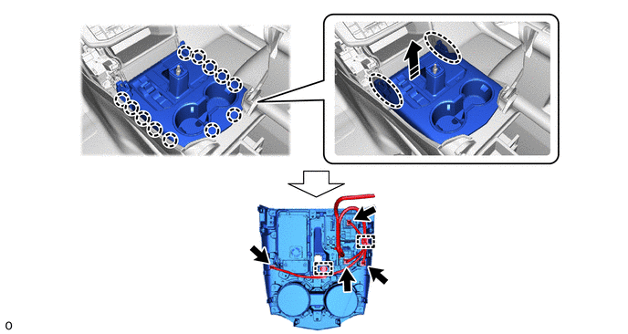
4.REMOVE UPPER CONSOLE PANEL ASSEMBLY
- HINT:
-
The illustrations are representative examples, and details may differ.
|
|
Place Hands Here |
|
Remove in this Direction |
55395C 5.REMOVE INNER NO. 1 INSTRUMENT PANEL BRACKET COVER LH
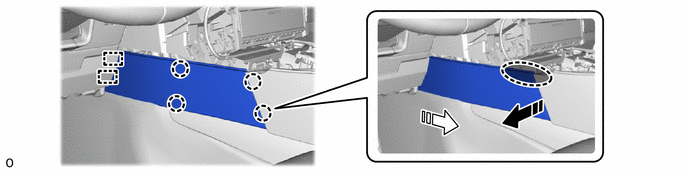
|
|
Place Hand Here |
|
Remove in this Direction (1) |
|
|
Remove in this Direction (2) | - | - |
55394D 6.REMOVE INNER NO. 1 INSTRUMENT PANEL BRACKET COVER RH
Use the same procedure described for the LH side.
58903A 7.REMOVE CONSOLE REAR END PANEL SUB-ASSEMBLY
- HINT:
-
The illustrations are representative examples, and details may differ.
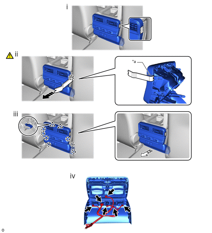
| *a | Cut Line | - | - |
|
|
Remove in this Direction (1) |
|
Remove in this Direction (2) |

|
Protective Tape | - | - |
Apply the protective tape as shown in the illustration.
Using moulding remover B, detach the claw as shown in the illustration.
- HINT:
-
Insert the moulding remover B under the cut line as shown in the illustration.
Detach the clip and claw as shown in the illustration.
Disconnect each connector and remove the console rear end panel sub-assembly.
55405B 8.REMOVE CENTER INSTRUMENT CLUSTER FINISH PANEL SUB-ASSEMBLY
- HINT:
-
The illustrations are representative examples, and details may differ.
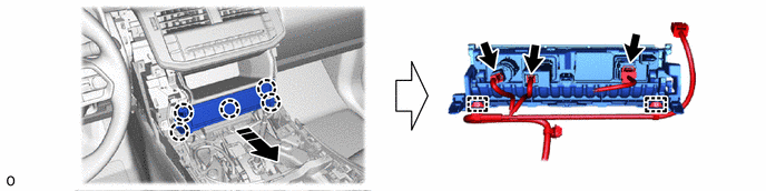
|
|
Remove in this Direction | - | - |
58901A 9.REMOVE REAR CONSOLE BOX SUB-ASSEMBLY
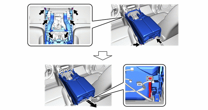
|
|
Remove in this Direction | - | - |