INTERIOR PANELS / TRIM FRONT CONSOLE BOX(w/ Cool Box) INSTALLATION
CAUTION / NOTICE / HINT
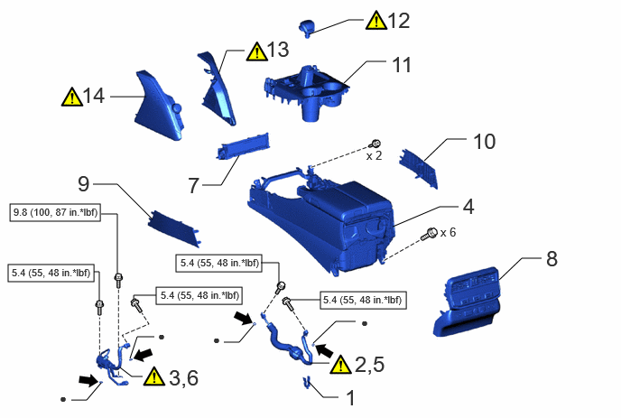
| Procedure | Part Name Code |

|

|

|
|
|---|---|---|---|---|---|
| 1 | PIPING CLAMP | - | - | - | - |
| 2 | INSTALL NO. 7 AIR CONDITIONING TUBE AND ACCESSORY ASSEMBLY | 88G10C | ( ) |
- | - |
| 3 | INSTALL NO. 8 AIR CONDITIONING TUBE AND ACCESSORY ASSEMBLY | 88G10D | () |
- | - |
| 4 | COOLING BOX ASSEMBLY | - | - | - | - |
| 5 | CONNECT NO. 7 AIR CONDITIONING TUBE AND ACCESSORY ASSEMBLY | 88G10C | () |
- | - |
| 6 | CONNECT NO. 8 AIR CONDITIONING TUBE AND ACCESSORY ASSEMBLY | 88G10D | () |
- | - |
| 7 | CENTER INSTRUMENT CLUSTER FINISH PANEL SUB-ASSEMBLY | 55405B | - | - | - |
| 8 | CONSOLE REAR END PANEL SUB-ASSEMBLY | 58903A | - | - | - |
| 9 | INNER NO. 1 INSTRUMENT PANEL BRACKET COVER LH | 55395C | - | - | - |
| 10 | INNER NO. 1 INSTRUMENT PANEL BRACKET COVER RH | 55394D | - | - | - |
| 11 | UPPER CONSOLE PANEL ASSEMBLY | - | - | - | - |
| 12 | SHIFT LEVER KNOB SUB-ASSEMBLY | 33504F | () |
- | - |
| 13 | LOWER NO. 2 INSTRUMENT PANEL PAD SUB-ASSEMBLY | 55403H | () |
- | - |
| 14 | INTEGRATION CONTROL AND PANEL SUB-ASSEMBLY | 84012 | () |
- | - |

|
N*m (kgf*cm, ft.*lbf): Specified torque | ● | Non-reusable part |

|
Compressor oil ND-OIL 8 or equivalent | - | - |
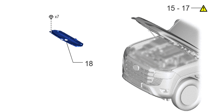
| Procedure | Part Name Code |
|
|
|
|
|---|---|---|---|---|---|
| 15 | CHARGE AIR CONDITIONING SYSTEM WITH REFRIGERANT | - | () |
- | - |
| 16 | WARM UP ENGINE | - | () |
- | - |
| 17 | INSPECT FOR REFRIGERANT LEAK | - | () |
- | - |
| 18 | UPPER RADIATOR SUPPORT SEAL | 53292A | - | - | - |
CAUTION / NOTICE / HINT
- HINT:
-
·
Use the same procedure for RHD and LHD vehicles.
·The procedure listed below is for LHD vehicles.
·A bolt without a torque specification is shown in the standard bolt chart.
Click hereGeneral>SPECIFICATIONS>STANDARD BOLT>SPECIFIED TORQUE FOR STANDARD BOLTS
PROCEDURE

 1.INSTALL PIPING CLAMP
88G10C 2.INSTALL NO. 7 AIR CONDITIONING TUBE AND ACCESSORY ASSEMBLY
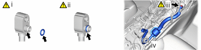
Remove the vinyl tape from the No. 7 air conditioning tube and accessory assembly and then apply a sufficient amount of compressor oil to a new O-ring and the fitting surface of the No. 7 air conditioning tube and accessory assembly and air conditioner unit assembly.
- Compressor Oil:
-
ND-OIL 8 or equivalent
Install the O-ring to the No. 7 air conditioning tube and accessory assembly.
- NOTICE:
-
Keep the O-rings and O-ring fitting surfaces free of foreign matter.
Install the No. 7 air conditioning tube and accessory assembly with the bolt.
- Torque:
- 5.4 N*m (55 kgf*cm, 48 in.*lbf)
- NOTICE:
-
Make sure not to cut the O-ring while installing it. (Cut O-rings cannot be installed.)
Attach the clamp.
88G10D 3.INSTALL NO. 8 AIR CONDITIONING TUBE AND ACCESSORY ASSEMBLY
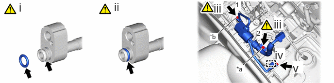
| *a | Bolt (A) | *b | Bolt (B) |
Remove the vinyl tape from the No. 8 air conditioning tube and accessory assembly and then apply a sufficient amount of compressor oil to a new O-ring and the fitting surface of the No. 8 air conditioning tube and accessory assembly and No. 4 air conditioning tube and accessory assembly.
- Compressor Oil:
-
ND-OIL 8 or equivalent
Install the O-ring to the No. 8 air conditioning tube and accessory assembly.
- NOTICE:
-
Keep the O-rings and O-ring fitting surfaces free of foreign matter.
Install the No. 8 air conditioning tube and accessory assembly with the 2 bolts and tighten the bolts in the order shown in the illustration.
- Torque:
- Bolt (A) : 9.8 N*m (100 kgf*cm, 87 in.*lbf)
- Bolt (B) : 5.4 N*m (55 kgf*cm, 48 in.*lbf)
- NOTICE:
-
Make sure not to cut the O-ring while installing it. (Cut O-rings cannot be installed.)
Attach the clamp.
Connect the connector.
4.INSTALL COOLING BOX ASSEMBLY
88G10C 5.CONNECT NO. 7 AIR CONDITIONING TUBE AND ACCESSORY ASSEMBLY
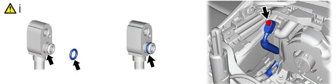
Connect the No. 7 air conditioning tube and accessory assembly using the following procedure.
1. Remove the vinyl tape from the No. 7 air conditioning tube and accessory assembly and then apply a sufficient amount of compressor oil to a new O-ring and the fitting surface of the No. 7 air conditioning tube and accessory assembly and cooling box assembly.
- Compressor Oil:
-
ND-OIL 8 or equivalent
2. Install the O-ring to the No. 7 air conditioning tube and accessory assembly.
- NOTICE:
-
Keep the O-rings and O-ring fitting surfaces free of foreign matter.
3. Connect the No. 7 air conditioning tube and accessory assembly with the bolt.
- Torque:
- 5.4 N*m (55 kgf*cm, 48 in.*lbf)
- NOTICE:
-
Make sure not to cut the O-ring while installing it. (Cut O-rings cannot be installed.)
88G10D 6.CONNECT NO. 8 AIR CONDITIONING TUBE AND ACCESSORY ASSEMBLY
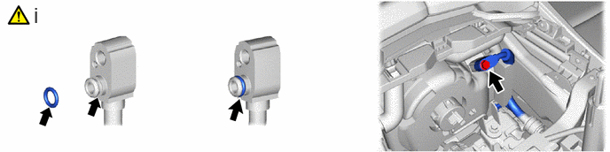
Connect the No. 8 air conditioning tube and accessory assembly using the following procedure.
1. Remove the vinyl tape from the No. 8 air conditioning tube and accessory assembly and then apply a sufficient amount of compressor oil to a new O-ring and the fitting surface of the No. 8 air conditioning tube and accessory assembly and cooling box assembly.
- Compressor Oil:
-
ND-OIL 8 or equivalent
2. Install the O-ring to the No. 8 air conditioning tube and accessory assembly.
- NOTICE:
-
Keep the O-rings and O-ring fitting surfaces free of foreign matter.
3. Connect the No. 8 air conditioning tube and accessory assembly with the bolt.
- Torque:
- 5.4 N*m (55 kgf*cm, 48 in.*lbf)
- NOTICE:
-
Make sure not to cut the O-ring while installing it. (Cut O-rings cannot be installed.)
55405B 7.INSTALL CENTER INSTRUMENT CLUSTER FINISH PANEL SUB-ASSEMBLY
58903A 8.INSTALL CONSOLE REAR END PANEL SUB-ASSEMBLY
55395C 9.INSTALL INNER NO. 1 INSTRUMENT PANEL BRACKET COVER LH
55394D 10.INSTALL INNER NO. 1 INSTRUMENT PANEL BRACKET COVER RH
11.INSTALL UPPER CONSOLE PANEL ASSEMBLY
33504F 12.INSTALL SHIFT LEVER KNOB SUB-ASSEMBLY
|
|
for AC60F: Click here( ) for AJA0F: Click here( ) |
55403H 13.INSTALL LOWER NO. 2 INSTRUMENT PANEL PAD SUB-ASSEMBLY
|
|
Click here() |
84012 14.INSTALL INTEGRATION CONTROL AND PANEL SUB-ASSEMBLY
|
|
Click here() |
15. CHARGE AIR CONDITIONING SYSTEM WITH REFRIGERANT
16.WARM UP ENGINE
17.INSPECT FOR REFRIGERANT LEAK
53292A 18.INSTALL UPPER RADIATOR SUPPORT SEAL