Home › Steering › STEERING COLUMN › POWER TILT AND POWER TELESCOPIC STEERING COLUMN SYSTEM
RM38G0E _55 Steering _100923 STEERING COLUMN _0468603 POWER TILT AND POWER TELESCOPIC STEERING COLUMN SYSTEM C

STEERING COLUMN  POWER TILT AND POWER TELESCOPIC STEERING COLUMN SYSTEM  B261196  Telescopic Position Sensor or Telescopic Motor Circuit Component Internal Failure  


DESCRIPTION

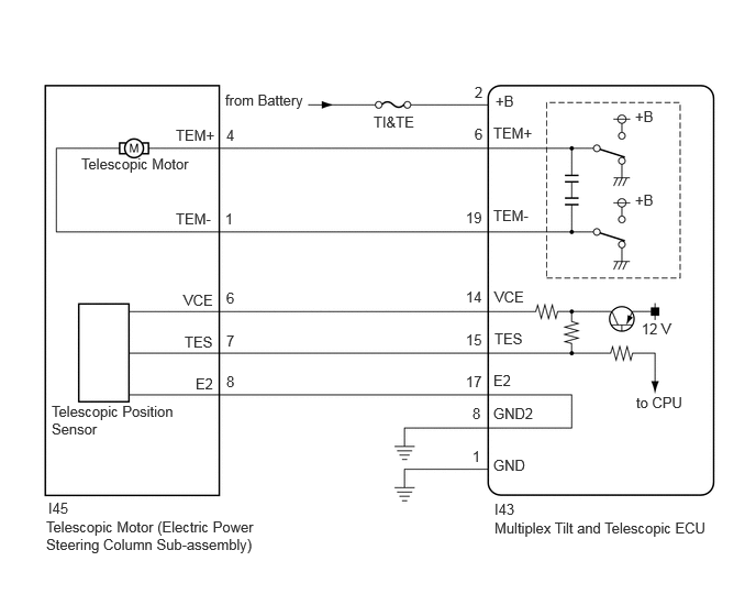
The telescopic motor (electric power steering column sub-assembly) is operated by the power source voltage supplied from the multiplex tilt and telescopic ECU and slides the electric power steering column sub-assembly forward and backward. The telescopic position sensor (Hall IC) in the telescopic motor (electric power steering column sub-assembly) detects the sliding position of the electric power steering column sub-assembly in the forward and backward directions and sends a signal to the multiplex tilt and telescopic ECU based on that sliding amount.

DTC No. Detection Item DTC Detection Condition Trouble Area DTC Output from Priority
B261196 Telescopic Position Sensor or Telescopic Motor Circuit Component Internal Failure Telescopic operation stops within the operation range while operating.
·

TI&TE Fuse

·

Telescopic position sensor (electric power steering column sub-assembly)

·

Telescopic motor (electric power steering column sub-assembly)

·

Harness or connector

·

Multiplex tilt and telescopic ECU


Tilt&Telescopic A

WIRING DIAGRAM

C244373E58
2.135,0.865 2.979,1.333 0.844,0.469 10 false from Battery 3.542,1.073 4.125,1.406 0.583,0.333 10 false TI&TE 4.698,0.875 5.042,1.104 0.344,0.229 10 false +B 4.5,0.792 4.604,0.938 0.104,0.146 10 false 2 1.667,1.198 2.177,1.49 0.51,0.292 10 false TEM+ 2.135,1.99 2.25,2.135 0.115,0.146 10 false 1 1.667,1.99 2.229,2.281 0.563,0.292 10 false TEM- 2.146,1.198 2.26,1.344 0.115,0.146 10 false 4 1.74,2.76 2.208,3.01 0.469,0.25 10 false VCE 2.146,2.74 2.25,2.906 0.104,0.167 10 false 6 1.75,3.156 2.208,3.458 0.458,0.302 10 false TES 2.146,3.146 2.26,3.313 0.115,0.167 10 false 7 1.854,3.552 2.208,3.865 0.354,0.313 10 false E2 2.146,3.531 2.26,3.698 0.115,0.167 10 false 8 0.771,1.469 2.01,1.729 1.24,0.26 10 false Telescopic Motor 4.677,1.177 5.146,1.417 0.469,0.24 10 false TEM+ 4.677,1.958 5.146,2.26 0.469,0.302 10 false TEM- 4.688,2.729 5.177,3.01 0.49,0.281 10 false VCE 4.688,3.125 5.146,3.375 0.458,0.25 10 false TES 4.677,3.521 5.021,3.76 0.344,0.24 10 false E2 0.49,3.813 1.781,4.219 1.292,0.406 10 false Telescopic Position Sensor 4.417,1.979 4.604,2.177 0.188,0.198 10 false 19 4.417,2.729 4.604,2.938 0.188,0.208 10 false 14 4.417,3.135 4.729,3.344 0.313,0.208 10 false 15 4.688,4.74 5.271,5.01 0.583,0.271 10 false I43 4.5,1.188 4.74,1.385 0.24,0.198 10 false 6 4.479,3.833 4.719,4.031 0.24,0.198 10 false 8 4.417,3.531 4.729,3.729 0.313,0.198 10 false 17 4.677,3.833 5.271,4.146 0.594,0.313 10 false GND2 4.479,4.24 4.719,4.438 0.24,0.198 10 false 1 4.677,4.323 5.271,4.604 0.594,0.281 10 false GND 6.021,1.021 6.333,1.219 0.313,0.198 10 false +B 6.021,1.813 6.333,2.01 0.313,0.198 10 false +B 6.083,3.031 6.521,3.354 0.438,0.323 10 false 12 V 6.031,3.729 6.604,4 0.573,0.271 10 false to CPU 4.688,4.917 6.948,5.26 2.26,0.344 10 false Multiplex Tilt and Telescopic ECU 0.438,4.906 2.49,5.281 2.052,0.375 10 false Telescopic Motor (Electric Power Steering Column Sub-assembly) 0.458,4.729 0.948,4.99 0.49,0.26 10 false I45

CAUTION / NOTICE / HINT

NOTICE:

Inspect the fuses for circuits related to this system before performing the following procedure.


PROCEDURE

1.PERFORM ACTIVE TEST USING GTS (TELESCOPIC MOTOR)
a.

Check that the steering column contracts and extends.

Body Electrical > Tilt&Telescopic > Active Test
Tester Display
Telescopic Motor
50004 406 42001
Body Electrical > Tilt&Telescopic > Active Test
Tester Display Measurement Item Control Range
Telescopic Motor Telescopic Operation LONG/SHORT
OK:

The steering column contracts and extends.


Result:
Proceed to
OK
NG


OK

2.CHECK HARNESS AND CONNECTOR (MULTIPLEX TILT AND TELESCOPIC ECU - TELESCOPIC POSITION SENSOR (ELECTRIC POWER STEERING COLUMN SUB-ASSEMBLY))

NG

6.CHECK HARNESS AND CONNECTOR (MULTIPLEX TILT AND TELESCOPIC ECU - BATTERY)
2.CHECK HARNESS AND CONNECTOR (MULTIPLEX TILT AND TELESCOPIC ECU - TELESCOPIC POSITION SENSOR (ELECTRIC POWER STEERING COLUMN SUB-ASSEMBLY))
a.

Disconnect the I43 multiplex tilt and telescopic ECU connector.


b.

Disconnect the I45 telescopic motor (electric power steering column sub-assembly) connector.
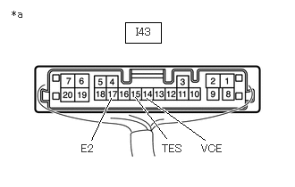

c.

Measure the resistance according to the value(s) in the table below.

Standard Resistance:
Tester Connection Condition Specified Condition

Click Location & Routing(I43,I45)Location & Routing

Click Connector(I43)Instrument Panel>Instrument Panel Wire / Mobile Wireless Charger Cord / No. 1 Navigation Wire / No. 2 Instrument Panel Wire / No. 5 Instrument Panel Wire / Telephone Computer Wire>Multiplex Tilt & Telescopic ECU

Click Connector(I45)Instrument Panel>Instrument Panel Wire / Mobile Wireless Charger Cord / No. 1 Navigation Wire / No. 2 Instrument Panel Wire / No. 5 Instrument Panel Wire / Telephone Computer Wire>Telescopic Motor (Steering Column Assembly)

I43-14 (VCE) - I45-6 (VCE) Always Below 1 Ω
I43-15 (TES) - I45-7 (TES) Always Below 1 Ω
I43-17 (E2) - I45-8 (E2) Always Below 1 Ω
I43-14 (VCE) or I45-6 (VCE) - Body ground Always 10 kΩ or higher
I43-15 (TES) or I45-7 (TES) - Body ground Always 10 kΩ or higher
I43-17 (E2) or I45-8 (E2) - Body ground Always 10 kΩ or higher


Result:
Proceed to
OK
NG


OK

3.CHECK HARNESS AND CONNECTOR (MULTIPLEX TILT AND TELESCOPIC ECU - BODY GROUND)

NG

REPAIR OR REPLACE HARNESS OR CONNECTOR

3.CHECK HARNESS AND CONNECTOR (MULTIPLEX TILT AND TELESCOPIC ECU - BODY GROUND)
a.

Disconnect the I43 multiplex tilt and telescopic ECU connector.


b.

Measure the resistance according to the value(s) in the table below.

Standard Resistance:
Tester Connection Condition Specified Condition

Click Location & Routing(I43)Location & Routing

Click Connector(I43)Instrument Panel>Instrument Panel Wire / Mobile Wireless Charger Cord / No. 1 Navigation Wire / No. 2 Instrument Panel Wire / No. 5 Instrument Panel Wire / Telephone Computer Wire>Multiplex Tilt & Telescopic ECU

I43-1 (GND) - Body ground Always Below 1 Ω
I43-8 (GND2) - Body ground Always Below 1 Ω


Result:
Proceed to
OK
NG


OK

4.CHECK MULTIPLEX TILT AND TELESCOPIC ECU (VCE, TES TERMINAL VOLTAGE)

NG

REPAIR OR REPLACE HARNESS OR CONNECTOR

4.CHECK MULTIPLEX TILT AND TELESCOPIC ECU (VCE, TES TERMINAL VOLTAGE)
a.

Reconnect the I43 multiplex tilt and telescopic ECU connector.


b.

Disconnect the I45 telescopic motor (electric power steering column sub-assembly) connector.
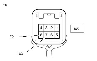

c.
C401145C44
1.458,0.26 1.875,0.5 0.417,0.24 1.063,1.635 1.292,1.146 true 2.385,1.635 1.708,1.146 true 1.938,1.615 1.573,1.135 true 1.583,0.302 2.042,0.5 0.458,0.198 10 false I43 0.948,1.667 1.406,1.865 0.458,0.198 10 false E2 1.885,1.667 2.344,1.865 0.458,0.198 10 false TES 2.344,1.667 2.802,1.865 0.458,0.198 10 false VCE 0.135,0.094 0.448,0.292 0.313,0.198 10 false *a
*a Component with harness connected
(Multiplex Tilt and Telescopic ECU)


Measure the voltage according to the value(s) in the table below.

Standard Voltage:
Tester Connection Condition Specified Condition

Click Location & Routing(I43)Location & Routing

Click Connector(I43)Instrument Panel>Instrument Panel Wire / Mobile Wireless Charger Cord / No. 1 Navigation Wire / No. 2 Instrument Panel Wire / No. 5 Instrument Panel Wire / Telephone Computer Wire>Multiplex Tilt & Telescopic ECU

I43-14 (VCE) - I43-17 (E2) Ignition switch ON 8 to 14 V
I43-15 (TES) - I43-17 (E2) Ignition switch ON 8 to 14 V


Result:
Proceed to
OK
NG


OK

5.CHECK TELESCOPIC POSITION SENSOR (ELECTRIC POWER STEERING COLUMN SUB-ASSEMBLY)

NG

REPLACE MULTIPLEX TILT AND TELESCOPIC ECU

5.CHECK TELESCOPIC POSITION SENSOR (ELECTRIC POWER STEERING COLUMN SUB-ASSEMBLY)
a.

Reconnect the I43 multiplex tilt and telescopic ECU connector.


b.

Reconnect the I45 telescopic motor (electric power steering column sub-assembly) connector.


c.
C373326C18
2.5,0.896 2.969,1.167 0.469,0.271 0.938,1.865 1.594,1.344 true 0.604,1.323 1.385,1.26 true 0.115,0.104 0.427,0.302 0.313,0.198 10 false *a 2.625,0.969 3.146,1.271 0.521,0.302 10 false I45 0.344,1.25 0.656,1.448 0.313,0.198 10 false E2 0.594,1.844 0.906,2.042 0.313,0.198 10 false TES
*a Component with harness connected
(Telescopic Motor (Electric Power Steering Column Sub-assembly))


Measure the voltage according to the value(s) in the table below.

Standard Voltage:
Tester Connection Condition Specified Condition

Click Location & Routing(I45)Location & Routing

Click Connector(I45)Instrument Panel>Instrument Panel Wire / Mobile Wireless Charger Cord / No. 1 Navigation Wire / No. 2 Instrument Panel Wire / No. 5 Instrument Panel Wire / Telephone Computer Wire>Telescopic Motor (Steering Column Assembly)

I45-7 (TES) - I45-8 (E2) Steering column contracting or extending Pulse generation
High: 8 to 14 V
Low: Below 1 V


Result:
Proceed to
OK
NG


OK

REPLACE MULTIPLEX TILT AND TELESCOPIC ECU

NG

6.CHECK HARNESS AND CONNECTOR (MULTIPLEX TILT AND TELESCOPIC ECU - BATTERY)
a.

Disconnect the I43 multiplex tilt and telescopic ECU connector.


b.

Measure the voltage according to the value(s) in the table below.

Standard Voltage:
Tester Connection Condition Specified Condition

Click Location & Routing(I43)Location & Routing

Click Connector(I43)Instrument Panel>Instrument Panel Wire / Mobile Wireless Charger Cord / No. 1 Navigation Wire / No. 2 Instrument Panel Wire / No. 5 Instrument Panel Wire / Telephone Computer Wire>Multiplex Tilt & Telescopic ECU

I43-2 (+B) - Body ground Ignition switch off 11 to 14 V


Result:
Proceed to
OK
NG


OK

7.CHECK HARNESS AND CONNECTOR (MULTIPLEX TILT AND TELESCOPIC ECU - BODY GROUND)

NG

REPAIR OR REPLACE HARNESS OR CONNECTOR

7.CHECK HARNESS AND CONNECTOR (MULTIPLEX TILT AND TELESCOPIC ECU - BODY GROUND)
a.

Disconnect the I43 multiplex tilt and telescopic ECU connector.


b.

Measure the resistance according to the value(s) in the table below.

Standard Resistance:
Tester Connection Condition Specified Condition

Click Location & Routing(I43)Location & Routing

Click Connector(I43)Instrument Panel>Instrument Panel Wire / Mobile Wireless Charger Cord / No. 1 Navigation Wire / No. 2 Instrument Panel Wire / No. 5 Instrument Panel Wire / Telephone Computer Wire>Multiplex Tilt & Telescopic ECU

I43-1 (GND) - Body ground Always Below 1 Ω
I43-8 (GND2) - Body ground Always Below 1 Ω


Result:
Proceed to
OK
NG


OK

8.CHECK HARNESS AND CONNECTOR (MULTIPLEX TILT AND TELESCOPIC ECU - TELESCOPIC MOTOR (ELECTRIC POWER STEERING COLUMN SUB-ASSEMBLY))

NG

REPAIR OR REPLACE HARNESS OR CONNECTOR

8.CHECK HARNESS AND CONNECTOR (MULTIPLEX TILT AND TELESCOPIC ECU - TELESCOPIC MOTOR (ELECTRIC POWER STEERING COLUMN SUB-ASSEMBLY))
a.

Disconnect the I43 multiplex tilt and telescopic ECU connector.


b.

Disconnect the I45 telescopic motor (electric power steering column sub-assembly) connector.


c.

Measure the resistance according to the value(s) in the table below.

Standard Resistance:
Tester Connection Condition Specified Condition

Click Location & Routing(I43,I45)Location & Routing

Click Connector(I43)Instrument Panel>Instrument Panel Wire / Mobile Wireless Charger Cord / No. 1 Navigation Wire / No. 2 Instrument Panel Wire / No. 5 Instrument Panel Wire / Telephone Computer Wire>Multiplex Tilt & Telescopic ECU

Click Connector(I45)Instrument Panel>Instrument Panel Wire / Mobile Wireless Charger Cord / No. 1 Navigation Wire / No. 2 Instrument Panel Wire / No. 5 Instrument Panel Wire / Telephone Computer Wire>Telescopic Motor (Steering Column Assembly)

I43-6 (TEM+) - I45-4 (TEM+) Always Below 1 Ω
I43-19 (TEM-) - I45-1 (TEM-) Always Below 1 Ω
I43-6 (TEM+) or I45-4 (TEM+) - Body ground Always 10 kΩ or higher
I43-19 (TEM-) or I45-1 (TEM-) - Body ground Always 10 kΩ or higher


Result:
Proceed to
OK
NG


OK

9.CHECK TELESCOPIC MOTOR (ELECTRIC POWER STEERING COLUMN SUB-ASSEMBLY)

NG

REPAIR OR REPLACE HARNESS OR CONNECTOR

9.CHECK TELESCOPIC MOTOR (ELECTRIC POWER STEERING COLUMN SUB-ASSEMBLY)

OK

REPLACE MULTIPLEX TILT AND TELESCOPIC ECU

NG