Home › Audio / Visual / Telematics › AUDIO / VIDEO › AUDIO AND VISUAL SYSTEM (for Radio and Display Type, except 12.3 Inch Display)
RM38G0E _56 Audio / Visual / Telematics _100606 AUDIO / VIDEO _0467497 AUDIO AND VISUAL SYSTEM(for Radio and Display Type, except 12.3 Inch Display) J

AUDIO / VIDEO  AUDIO AND VISUAL SYSTEM(for Radio and Display Type, except 12.3 Inch Display)  Radio Broadcast cannot be Received or Poor Reception  


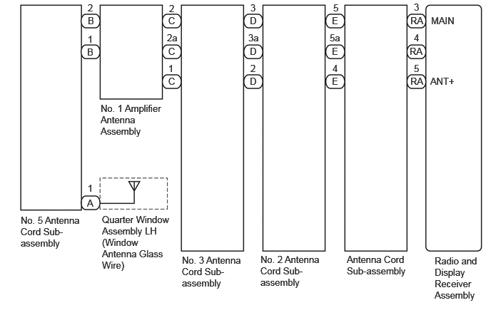
WIRING DIAGRAM

w/ DAB Function
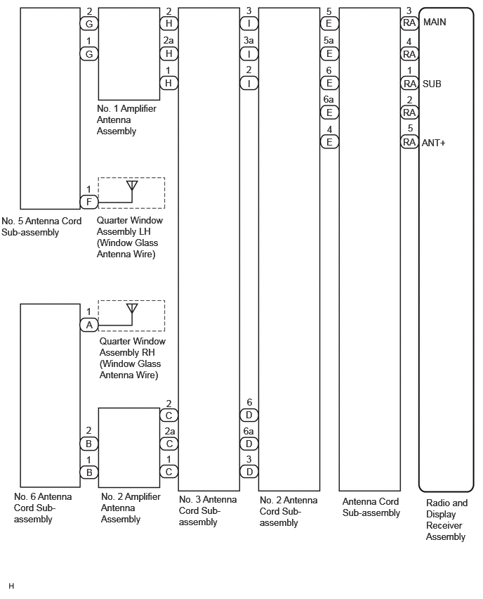

E462682E03
6.323,7.365 6.958,8.167 0.635,0.802 10 false Radio and Display Receiver Assembly 0.208,7.271 1.104,7.854 0.896,0.583 10 false No. 6 Antenna Cord Sub-assembly 5.083,7.344 5.969,7.958 0.885,0.615 10 false Antenna Cord Sub-assembly 3.854,7.323 4.75,7.938 0.896,0.615 10 false No. 2 Antenna Cord Sub-assembly 0.021,3.188 1.25,3.594 1.229,0.406 10 false No. 5 Antenna Cord Sub-assembly 1.438,1.521 2.365,2.219 0.927,0.698 10 false No. 1 Amplifier Antenna Assembly 1.281,2.906 1.594,3.104 0.313,0.198 10 false F 5.979,0.719 6.292,0.917 0.313,0.198 10 false RA 5.99,1.156 6.302,1.354 0.313,0.198 10 false RA 5.979,1.583 6.292,1.781 0.313,0.198 10 false RA 5.979,2.021 6.292,2.219 0.313,0.198 10 false RA 1.271,0.271 1.583,0.469 0.313,0.198 10 false G 1.281,4.729 1.594,4.927 0.313,0.198 10 false A 1.281,6.917 1.594,7.115 0.313,0.198 10 false B 3.677,0.26 3.99,0.458 0.313,0.198 10 false I 3.677,0.719 3.99,0.917 0.313,0.198 10 false I 3.677,1.156 3.99,1.354 0.313,0.198 10 false I 4.833,0.26 5.146,0.458 0.313,0.198 10 false E 4.844,0.708 5.156,0.906 0.313,0.198 10 false E 4.844,1.146 5.156,1.344 0.313,0.198 10 false E 4.844,1.583 5.156,1.781 0.313,0.198 10 false E 4.844,2.021 5.156,2.219 0.313,0.198 10 false E 5.979,0.25 6.292,0.448 0.313,0.198 10 false RA 3.646,6.063 3.958,6.26 0.313,0.198 10 false D 3.646,6.49 3.958,6.688 0.313,0.198 10 false D 3.656,6.906 3.969,7.104 0.313,0.198 10 false D 6.031,0.073 6.344,0.271 0.313,0.198 10 false 3 6.031,0.531 6.344,0.729 0.313,0.198 10 false 4 6.042,0.958 6.354,1.156 0.313,0.198 10 false 1 6.042,1.396 6.354,1.594 0.313,0.198 10 false 2 6.052,1.813 6.365,2.01 0.313,0.198 10 false 5 6.26,2.031 6.781,2.302 0.521,0.271 10 false ANT+ 6.281,0.24 6.802,0.51 0.521,0.271 10 false MAIN 6.271,1.156 6.792,1.427 0.521,0.271 10 false SUB 4.844,0.083 5.156,0.281 0.313,0.198 10 false 5 4.802,0.51 5.115,0.708 0.313,0.198 10 false 5a 4.844,0.958 5.156,1.156 0.313,0.198 10 false 6 4.802,1.385 5.115,1.583 0.313,0.198 10 false 6a 4.854,1.833 5.177,2.042 0.323,0.208 10 false 4 3.656,0.073 3.969,0.271 0.313,0.198 10 false 3 3.615,0.51 3.927,0.708 0.313,0.198 10 false 3a 3.656,0.948 3.979,1.156 0.323,0.208 10 false 2 3.656,6.719 3.979,6.927 0.323,0.208 10 false 3 3.667,5.875 3.979,6.073 0.313,0.198 10 false 6 3.615,6.302 3.927,6.5 0.313,0.198 10 false 6a 1.281,6.729 1.594,6.927 0.313,0.198 10 false 1 1.281,4.531 1.594,4.729 0.313,0.198 10 false 1 1.292,0.083 1.604,0.281 0.313,0.198 10 false 2 1.281,2.719 1.604,2.927 0.323,0.208 10 false 1 1.5,7.271 2.417,7.906 0.917,0.635 10 false No. 2 Amplifier Antenna Assembly 2.656,7.313 3.552,7.927 0.896,0.615 10 false No. 3 Antenna Cord Sub-assembly 2.427,0.51 2.74,0.708 0.313,0.198 10 false 2a 2.469,0.083 2.792,0.292 0.323,0.208 10 false 2 2.458,0.958 2.781,1.167 0.323,0.208 10 false 1 2.458,0.26 2.781,0.469 0.323,0.208 10 false H 2.458,0.708 2.781,0.917 0.323,0.208 10 false H 2.448,1.146 2.771,1.354 0.323,0.208 10 false H 2.469,5.896 2.792,6.104 0.323,0.208 10 false 2 2.448,6.302 2.771,6.51 0.323,0.208 10 false 2a 2.469,6.719 2.781,6.917 0.313,0.198 10 false 1 2.458,6.073 2.771,6.271 0.313,0.198 10 false C 2.469,6.49 2.781,6.688 0.313,0.198 10 false C 2.458,6.906 2.771,7.104 0.313,0.198 10 false C 1.271,0.719 1.583,0.917 0.313,0.198 10 false G 1.271,6.49 1.583,6.688 0.313,0.198 10 false B 1.281,6.292 1.594,6.49 0.313,0.198 10 false 2 1.281,0.521 1.604,0.729 0.323,0.208 10 false 1 1.438,3.177 2.552,3.969 1.115,0.792 10 false Quarter Window Assembly LH (Window Glass Antenna Wire) 1.479,4.969 2.594,5.76 1.115,0.792 10 false Quarter Window Assembly RH (Window Glass Antenna Wire)


w/o DAB Function


E464152E01
6.344,3.729 7,4.531 0.656,0.802 10 false Radio and Display Receiver Assembly 5.063,3.708 5.979,4.177 0.917,0.469 10 false Antenna Cord Sub-assembly 3.802,3.708 4.708,4.333 0.906,0.625 10 false No. 2 Antenna Cord Sub-assembly 2.656,3.719 3.563,4.344 0.906,0.625 10 false No. 3 Antenna Cord Sub-assembly 1.469,1.5 2.375,2.125 0.906,0.625 10 false No. 1 Amplifier Antenna Assembly 0.302,3.135 1.208,3.76 0.906,0.625 10 false No. 5 Antenna Cord Sub-assembly 1.271,2.885 1.5,3.083 0.229,0.198 10 false A 1.49,3.125 2.49,4.073 1,0.948 10 false Quarter Window Assembly LH (Window Antenna Glass Wire) 1.271,0.677 1.5,0.875 0.229,0.198 10 false B 1.281,0.219 1.51,0.417 0.229,0.198 10 false B 2.458,0.219 2.688,0.417 0.229,0.198 10 false C 2.458,0.667 2.688,0.865 0.229,0.198 10 false C 2.458,1.104 2.688,1.302 0.229,0.198 10 false C 3.646,0.219 3.875,0.417 0.229,0.198 10 false D 3.646,0.667 3.875,0.865 0.229,0.198 10 false D 3.646,1.104 3.875,1.302 0.229,0.198 10 false D 4.844,1.104 5.073,1.302 0.229,0.198 10 false E 4.844,0.667 5.073,0.865 0.229,0.198 10 false E 4.844,0.219 5.073,0.417 0.229,0.198 10 false E 5.99,0.219 6.219,0.417 0.229,0.198 10 false RA 5.979,0.667 6.208,0.865 0.229,0.198 10 false RA 5.99,1.104 6.219,1.302 0.229,0.198 10 false RA 1.281,2.667 1.51,2.865 0.229,0.198 10 false 1 1.281,0.49 1.51,0.688 0.229,0.198 10 false 1 2.469,0.042 2.698,0.24 0.229,0.198 10 false 2 1.281,0.031 1.51,0.229 0.229,0.198 10 false 2 2.438,0.469 2.667,0.667 0.229,0.198 10 false 2a 2.458,0.917 2.688,1.115 0.229,0.198 10 false 1 6.292,0.219 6.813,0.417 0.521,0.198 10 false MAIN 6.281,1.104 6.802,1.302 0.521,0.198 10 false ANT+ 6.042,0.917 6.271,1.115 0.229,0.198 10 false 5 6.042,0.021 6.271,0.219 0.229,0.198 10 false 3 6.042,0.469 6.271,0.667 0.229,0.198 10 false 4 4.865,0.031 5.094,0.229 0.229,0.198 10 false 5 4.813,0.469 5.042,0.667 0.229,0.198 10 false 5a 4.854,0.917 5.083,1.115 0.229,0.198 10 false 4 3.656,0.031 3.885,0.229 0.229,0.198 10 false 3 3.625,0.469 3.854,0.667 0.229,0.198 10 false 3a 3.656,0.917 3.885,1.115 0.229,0.198 10 false 2


CAUTION / NOTICE / HINT

HINT:

Depending on the parts that are replaced during vehicle inspection or maintenance, performing initialization, registration or calibration may be needed. Refer to Precaution for Audio and Visual System.

Click hereAudio / Visual / Telematics>AUDIO / VIDEO>AUDIO AND VISUAL SYSTEM (for Radio and Display Type, except 12.3 Inch Display)>PRECAUTION


PROCEDURE

1.CHECK RADIO AND DISPLAY RECEIVER ASSEMBLY
a.

Check the radio automatic station search function by activating it.

OK:

Automatic station search function stops on a station.


Result:
Proceed to
OK
NG


OK

NG

2.CHECK OPTIONAL COMPONENTS
a.

Check if any optional components that may decrease reception capacity, such as sunshade film or a telephone antenna, are installed.

OK:

Optional components are not installed.


NOTICE:

Do not remove optional components without the permission of the customer.


Result:
Proceed to
OK
NG


OK

3.CHECK RADIO AND DISPLAY RECEIVER ASSEMBLY

NG

REMOVE OPTIONAL COMPONENTS AND CHECK AGAIN (SEE NOTICE ABOVE)

3.CHECK RADIO AND DISPLAY RECEIVER ASSEMBLY
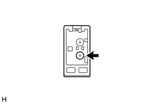
a.
E245523

Preparation for check

i.

Disconnect the RA radio and display receiver assembly connector.


b.

Check for noise

i.

Turn the ignition switch to ON with the radio and display receiver assembly connector connected.


ii.

Turn the radio and display receiver assembly on and tune into AM mode.


iii.

Place a screwdriver, thin wire or other metal object on the radio and display receiver assembly antenna jack and check that noise can be heard from the speakers.

OK:

Noise can be heard from the speakers.


Result:
Proceed to
OK
NG


OK

4.CHECK MODEL

NG

4.CHECK MODEL
a.

Choose the model to be inspected.


Result:
Result Proceed to
w/ DAB Function A
w/o DAB Function B


A

5.CHECK QUARTER WINDOW ASSEMBLY (WINDOW GLASS ANTENNA WIRE)

B

14.CHECK QUARTER WINDOW ASSEMBLY (WINDOW GLASS ANTENNA WIRE)
5.CHECK QUARTER WINDOW ASSEMBLY (WINDOW GLASS ANTENNA WIRE)
a.

Inspect the quarter window assembly (window glass antenna wire).

Click hereAudio / Visual / Telematics>AUDIO / VIDEO>WINDOW GLASS ANTENNA WIRE>ON-VEHICLE INSPECTION


Result:
Proceed to
OK
NG


OK

6.INSPECT RADIO AND DISPLAY RECEIVER ASSEMBLY

NG

REPAIR QUARTER WINDOW ASSEMBLY (WINDOW GLASS ANTENNA WIRE)

6.INSPECT RADIO AND DISPLAY RECEIVER ASSEMBLY
a.
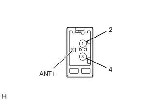
E188455E31
1.552,1.104 1.146,1.479 true 0.844,1.51 1.24,1.677 0.396,0.167 10 ANT+

Disconnect the RA radio and display receiver assembly connector.


b.

Measure the voltage according to the value(s) in the table below.

Standard Voltage:
Tester Connection Switch Condition Specified Condition
5 (ANT+) - Body ground Ignition switch ACC, radio switch on and FM or AM selected 11 to 14 V


Result:
Proceed to
OK
NG


OK

7.CHECK ANTENNA CORD SUB-ASSEMBLY

NG

7.CHECK ANTENNA CORD SUB-ASSEMBLY
a.
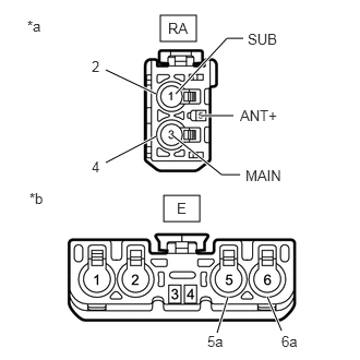
E367065C01
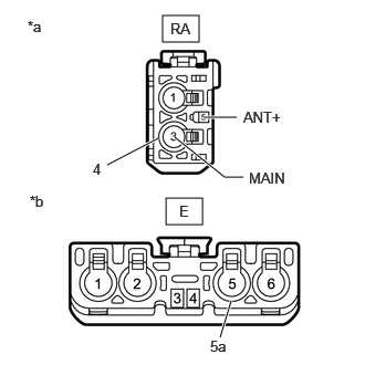
1.531,0.146 1.875,0.396 0.344,0.25 1.563,1.865 1.906,2.115 0.344,0.25 1.01,0.667 1.49,0.896 true 1.01,1.552 1.49,1.302 true 1.677,0.896 2.167,0.365 2.167,0.365 2.323,0.365 true 1.917,1.104 2.229,1.104 true 1.646,1.292 2.115,1.667 2.115,1.667 2.292,1.667 true 2.688,3.156 2.552,2.833 true 2.073,3.177 2.177,2.833 true 1.604,0.188 1.854,0.354 0.25,0.167 10 false RA 1.688,1.906 1.833,2.083 0.146,0.177 10 false E 0.26,0.167 0.438,0.354 0.177,0.188 10 false *a 0.281,1.813 0.458,2 0.177,0.188 10 false *b 0.875,0.552 0.99,0.74 0.115,0.188 10 false 2 0.875,1.51 0.99,1.698 0.115,0.188 10 false 4 2.365,0.292 2.688,0.469 0.323,0.177 10 false SUB 2.292,1.021 2.688,1.188 0.396,0.167 10 false ANT+ 2.344,1.594 2.74,1.76 0.396,0.167 10 false MAIN 2.688,3.177 2.885,3.354 0.198,0.177 10 false 6a 1.979,3.177 2.177,3.354 0.198,0.177 10 false 5a
*a Front view of wire harness connector
(to Radio and Display Receiver Assembly)
*b Front view of wire harness connector
(to No. 2 Antenna Cord Sub-assembly)


Disconnect the antenna connector from the radio and display receiver assembly.


b.

Disconnect the antenna connector from the No. 2 antenna cord sub-assembly.


c.

Measure the resistance according to the value(s) in the table below.

Standard Resistance:
Tester Connection Condition Specified Condition
RA-3 (MAIN) - E-5 Always Below 1 Ω
RA-4 - E-5a Always Below 1 Ω
RA-1 (SUB) - E-6 Always Below 1 Ω
RA-2 - E-6a Always Below 1 Ω
RA-5 (ANT+) - E-4 Always Below 1 Ω
RA-3 (MAIN) - Body ground Always 10 kΩ or higher
RA-1 (SUB) - Body ground Always 10 kΩ or higher
RA-5 (ANT+) - Body ground Always 10 kΩ or higher


Result:
Proceed to
OK
NG


OK

8.CHECK NO. 2 ANTENNA CORD SUB-ASSEMBLY

NG

8.CHECK NO. 2 ANTENNA CORD SUB-ASSEMBLY
a.
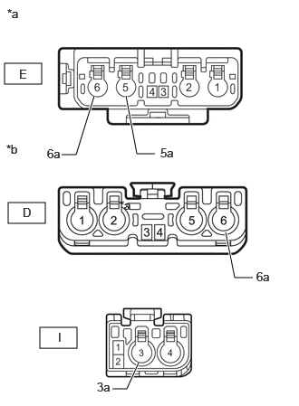
E462692C01
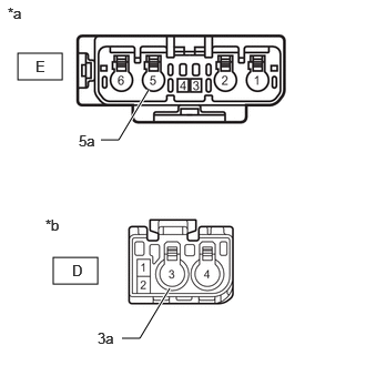
0.052,0.729 0.479,0.969 0.427,0.24 0.094,2.333 0.521,2.573 0.427,0.24 0.458,3.771 0.885,4.01 0.427,0.24 2.906,3.198 2.698,3.198 2.698,3.198 2.594,2.677 true 1.781,1.771 1.573,1.771 1.573,1.771 1.448,1.104 true 0.708,1.781 0.875,1.781 0.875,1.781 1.083,1.104 true 1.292,4.479 1.458,4.479 1.458,4.479 1.594,4.177 true 1.375,2.281 1.688,2.479 0.313,0.198 10 false *a 0.083,0.073 0.396,0.271 0.313,0.198 10 false *a 0.073,1.635 0.385,1.833 0.313,0.198 10 false *b 0.219,0.771 0.531,0.969 0.313,0.198 10 false E 0.26,2.365 0.573,2.563 0.313,0.198 10 false D 0.667,3.802 0.979,4 0.313,0.198 10 false I 1.115,4.375 1.427,4.573 0.313,0.198 10 false 3a 2.948,3.104 3.26,3.302 0.313,0.198 10 false 6a 1.844,1.677 2.156,1.875 0.313,0.198 10 false 5a 0.542,1.688 0.854,1.885 0.313,0.198 10 false 6a
*a Front view of wire harness connector
(to Antenna Cord Sub-assembly)
*b Front view of wire harness connector
(to No. 3 Antenna Cord Sub-assembly)


Disconnect the antenna connector from the antenna cord sub-assembly.


b.

Disconnect the antenna connector from the No. 3 amplifier antenna assembly.


c.

Measure the resistance according to the value(s) in the table below.

Standard Resistance:
Tester Connection Condition Specified Condition
E-5 - I-3 Always Below 1 Ω
E-5a- I-3a Always Below 1 Ω
E-4 - I-2 Always Below 1 Ω
E-6 - D-6 Always Below 1 Ω
E-6a - D-6a Always Below 1 Ω
E-4 - D-3 Always Below 1 Ω
E-5 - Body ground Always 10 kΩ or higher
E-6 - Body ground Always 10 kΩ or higher
E-4 - Body ground Always 10 kΩ or higher


Result:
Proceed to
OK
NG


OK

9.CHECK NO. 3 ANTENNA CORD SUB-ASSEMBLY

NG

9.CHECK NO. 3 ANTENNA CORD SUB-ASSEMBLY
a.
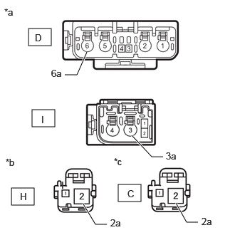
E462691C01
0.417,0.417 0.75,0.667 0.333,0.25 0.469,1.604 0.802,1.854 0.333,0.25 0.167,2.75 0.5,3 0.333,0.25 1.729,2.698 2.063,2.948 0.333,0.25 0.948,1.094 1.125,1.094 1.125,1.094 1.271,0.76 true 2.385,2.292 2.219,2.292 2.219,2.292 1.927,1.979 true 1.563,3.281 1.396,3.281 1.396,3.281 1.208,2.969 true 2.896,3.25 2.729,3.25 2.729,3.25 2.573,2.969 true 0.063,0.094 0.375,0.292 0.313,0.198 10 false *a 0.083,2.292 0.396,2.49 0.313,0.198 10 false *b 0.51,0.469 0.823,0.667 0.313,0.198 10 false D 0.604,1.667 0.917,1.865 0.313,0.198 10 false I 0.896,2.625 1.208,2.823 0.313,0.198 10 false I 1.667,2.281 1.979,2.479 0.313,0.198 10 false *c 0.292,2.792 0.604,2.99 0.313,0.198 10 false H 1.865,2.75 2.177,2.948 0.313,0.198 10 false C 0.75,0.99 1.063,1.188 0.313,0.198 10 false 6a 2.427,2.198 2.74,2.396 0.313,0.198 10 false 3a 1.615,3.177 1.927,3.375 0.313,0.198 10 false 2a 2.948,3.156 3.26,3.354 0.313,0.198 10 false 2a
*a Front view of wire harness connector
(to No. 2 Antenna Cord Sub-assembly)
*b Front view of wire harness connector
(to No. 1 Amplifier Antenna Assembly)
*c Front view of wire harness connector
(to No. 2 Amplifier Antenna Assembly)


Disconnect the antenna connector from the No. 2 antenna cord sub-assembly.


b.

Disconnect the antenna connector from the No. 1 amplifier antenna assembly.


c.

Disconnect the antenna connector from the No. 2 amplifier antenna assembly.


d.

Measure the resistance according to the value(s) in the table below.

Standard Resistance:
Tester Connection Condition Specified Condition
I-3 - H-2 Always Below 1 Ω
I-3a - H-2a Always Below 1 Ω
I-2 - H-1 Always Below 1 Ω
D-6 - C-2 Always Below 1 Ω
D-6a - C-2a Always Below 1 Ω
D-3 - C-1 Always Below 1 Ω
I-3 - Body ground Always 10 kΩ or higher
I-3a - Body ground Always 10 kΩ or higher
I-2 - Body ground Always 10 kΩ or higher
D-6 - Body ground Always 10 kΩ or higher
D-6a - Body ground Always 10 kΩ or higher
D-3 - Body ground Always 10 kΩ or higher


Result:
Proceed to
OK
NG


OK

10.CHECK NO. 5 ANTENNA CORD SUB-ASSEMBLY

NG

10.CHECK NO. 5 ANTENNA CORD SUB-ASSEMBLY
a.
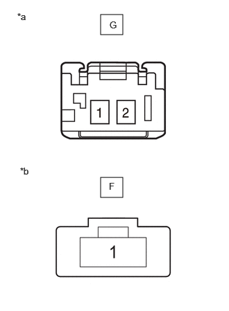
E464135C01
1.51,0.219 1.844,0.521 0.333,0.302 1.51,2.667 1.844,2.969 0.333,0.302 0.26,0.167 0.573,0.365 0.313,0.198 10 false *a 0.302,2.49 0.615,2.688 0.313,0.198 10 false *b 1.635,2.719 1.948,2.917 0.313,0.198 10 false F 1.646,0.292 1.958,0.49 0.313,0.198 10 false G
*a Front view of wire harness connector
(to No. 1 Amplifier Antenna Assembly)
*b Front view of wire harness connector
(to Quarter Window Assembly LH [Window Glass Antenna Wire])


Disconnect the antenna connector from the No. 1 amplifier antenna assembly.


b.

Disconnect the antenna connector from the quarter window assembly LH (window glass antenna wire).


c.

Measure the resistance according to the value(s) in the table below.

Standard Resistance:
Tester Connection Condition Specified Condition
G-2 - F-1 Always Below 1 Ω
G-2 - Body ground Always 10 kΩ or higher


Result:
Proceed to
OK
NG


OK

11.CHECK NO. 6 ANTENNA CORD SUB-ASSEMBLY

NG

REPLACE NO. 5 ANTENNA CORD SUB-ASSEMBLY

11.CHECK NO. 6 ANTENNA CORD SUB-ASSEMBLY
a.
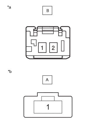
E464135C02
1.51,0.219 1.844,0.521 0.333,0.302 1.51,2.677 1.844,2.979 0.333,0.302 0.26,0.167 0.573,0.365 0.313,0.198 10 false *a 0.281,2.448 0.594,2.646 0.313,0.198 10 false *b 1.625,2.74 1.938,2.948 0.313,0.208 10 false A 1.646,0.292 1.958,0.49 0.313,0.198 10 false B
*a Front view of wire harness connector
(to No. 2 Amplifier Antenna Assembly)
*b Front view of wire harness connector
(to Quarter Window Assembly RH [Window Glass Antenna Wire])


Disconnect the antenna connector from the No. 2 amplifier antenna assembly.


b.

Disconnect the antenna connector from the quarter window assembly RH (window glass antenna wire).


c.

Measure the resistance according to the value(s) in the table below.

Standard Resistance:
Tester Connection Condition Specified Condition
B-2 - A-1 Always Below 1 Ω
B-2 - Body ground Always 10 kΩ or higher


Result:
Proceed to
OK
NG


OK

12.CHECK NO. 1 AMPLIFIER ANTENNA ASSEMBLY

NG

REPLACE NO. 6 ANTENNA CORD SUB-ASSEMBLY

12.CHECK NO. 1 AMPLIFIER ANTENNA ASSEMBLY
a.

Replace the No. 1 amplifier antenna assembly with a new or known good one.

Click hereAudio / Visual / Telematics>AUDIO / VIDEO>AMPLIFIER ANTENNA>REMOVAL

OK:

Radio broadcasts can be received normally.


Result:
Proceed to
OK
NG


OK

END (NO. 1 AMPLIFIER ANTENNA ASSEMBLY IS DEFECTIVE)

NG

13.CHECK NO. 2 AMPLIFIER ANTENNA ASSEMBLY
a.

Replace the No. 2 amplifier antenna assembly with a new or known good one.

Click hereAudio / Visual / Telematics>AUDIO / VIDEO>AMPLIFIER ANTENNA>REMOVAL

OK:

Radio broadcasts can be received normally.


Result:
Proceed to
OK
NG


OK

END (NO. 2 AMPLIFIER ANTENNA ASSEMBLY IS DEFECTIVE)

NG

14.CHECK QUARTER WINDOW ASSEMBLY (WINDOW GLASS ANTENNA WIRE)
a.

Inspect the quarter window assembly (window glass antenna wire).

Click hereAudio / Visual / Telematics>AUDIO / VIDEO>WINDOW GLASS ANTENNA WIRE>ON-VEHICLE INSPECTION


Result:
Proceed to
OK
NG


OK

15.INSPECT RADIO AND DISPLAY RECEIVER ASSEMBLY

NG

REPAIR QUARTER WINDOW ASSEMBLY (WINDOW GLASS ANTENNA WIRE)

15.INSPECT RADIO AND DISPLAY RECEIVER ASSEMBLY
a.
E188455E31
1.552,1.104 1.146,1.479 true 0.844,1.51 1.24,1.677 0.396,0.167 10 ANT+

Disconnect the RA radio and display receiver assembly connector.


b.

Measure the voltage according to the value(s) in the table below.

Standard Voltage:
Tester Connection Switch Condition Specified Condition
5 (ANT+) - Body ground Ignition switch ACC, radio switch on and FM or AM selected 11 to 14 V


Result:
Proceed to
OK
NG


OK

16.CHECK ANTENNA CORD SUB-ASSEMBLY

NG

16.CHECK ANTENNA CORD SUB-ASSEMBLY
a.
E367065C03
1.531,0.146 1.875,0.396 0.344,0.25 1.563,1.865 1.906,2.115 0.344,0.25 1.01,1.552 1.49,1.302 true 1.917,1.104 2.229,1.104 true 1.646,1.292 2.115,1.667 2.115,1.667 2.292,1.667 true 2.073,3.177 2.177,2.833 true 1.604,0.188 1.854,0.354 0.25,0.167 10 false RA 1.688,1.906 1.833,2.083 0.146,0.177 10 false E 0.26,0.167 0.438,0.354 0.177,0.188 10 false *a 0.281,1.813 0.458,2 0.177,0.188 10 false *b 0.875,1.51 0.99,1.698 0.115,0.188 10 false 4 2.292,1.021 2.688,1.188 0.396,0.167 10 false ANT+ 2.344,1.594 2.74,1.76 0.396,0.167 10 false MAIN 1.979,3.177 2.177,3.354 0.198,0.177 10 false 5a
*a Front view of wire harness connector
(to Radio and Display Receiver Assembly)
*b Front view of wire harness connector
(to No. 2 Antenna Cord Sub-assembly)


Disconnect the antenna connector from the radio and display receiver assembly.


b.

Disconnect the antenna connector from the No. 2 antenna cord sub-assembly.


c.

Measure the resistance according to the value(s) in the table below.

Standard Resistance:
Tester Connection Condition Specified Condition
RA-3 (MAIN) - E-5 Always Below 1 Ω
RA-4 - E-5a Always Below 1 Ω
RA-5 (ANT+) - E-4 Always Below 1 Ω
RA-3 (MAIN) - Body ground Always 10 kΩ or higher
RA-5 (ANT+) - Body ground Always 10 kΩ or higher


Result:
Proceed to
OK
NG


OK

17.CHECK NO. 2 ANTENNA CORD SUB-ASSEMBLY

NG

17.CHECK NO. 2 ANTENNA CORD SUB-ASSEMBLY
a.
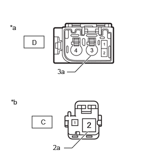
E464153C01
0.167,0.5 0.583,0.75 0.417,0.25 0.5,2.417 0.917,2.667 0.417,0.25 0.948,1.313 1.115,1.313 1.115,1.313 1.396,0.844 true 1.146,3.177 1.313,3.177 1.313,3.177 1.594,2.708 true 0.073,0.042 0.385,0.24 0.313,0.198 10 false *a 0.427,2.031 0.74,2.229 0.313,0.198 10 false *b 0.333,0.542 0.646,0.74 0.313,0.198 10 false E 0.677,2.458 0.99,2.656 0.313,0.198 10 false D 0.917,3.094 1.229,3.292 0.313,0.198 10 false 3a 0.74,1.24 1.052,1.438 0.313,0.198 10 false 5a
*a Front view of wire harness connector
(to Antenna Cord Sub-assembly)
*b Front view of wire harness connector
(to No. 3 Antenna Cord Sub-assembly)


Disconnect the antenna connector from the antenna cord sub-assembly.


b.

Disconnect the antenna connector from the No. 3 amplifier antenna assembly.


c.

Measure the resistance according to the value(s) in the table below.

Standard Resistance:
Tester Connection Condition Specified Condition
E-5 - D-3 Always Below 1 Ω
E-5a- D-3a Always Below 1 Ω
E-4 - D-2 Always Below 1 Ω
E-5 - Body ground Always 10 kΩ or higher
E-4 - Body ground Always 10 kΩ or higher


Result:
Proceed to
OK
NG


OK

18.CHECK NO. 3 ANTENNA CORD SUB-ASSEMBLY

NG

18.CHECK NO. 3 ANTENNA CORD SUB-ASSEMBLY
a.
E464155C01
0.5,0.75 0.917,1 0.417,0.25 0.667,2.417 1.083,2.667 0.417,0.25 1.333,3.083 1.5,3.083 1.5,3.083 1.833,2.74 true 1.396,1.5 1.563,1.5 1.563,1.5 1.896,1.156 true 0.667,0.802 0.979,1 0.313,0.198 10 false D 0.229,2.042 0.542,2.24 0.313,0.198 10 false *b 0.208,0.49 0.521,0.688 0.313,0.198 10 false *a 0.854,2.458 1.167,2.656 0.313,0.198 10 false C 1.104,2.99 1.417,3.188 0.313,0.198 10 false 2a 1.198,1.406 1.51,1.604 0.313,0.198 10 false 3a
*a Front view of wire harness connector
(to No. 2 Antenna Cord Sub-assembly)
*b Front view of wire harness connector
(to No. 1 Amplifier Antenna Assembly)


Disconnect the antenna connector from the No. 2 antenna cord sub-assembly.


b.

Disconnect the antenna connector from the No. 1 amplifier antenna assembly.


c.

Measure the resistance according to the value(s) in the table below.

Standard Resistance:
Tester Connection Condition Specified Condition
D-3 - C-2 Always Below 1 Ω
D-3a - C-2a Always Below 1 Ω
D-2 - C-1 Always Below 1 Ω
D-3 - Body ground Always 10 kΩ or higher
D-3a - Body ground Always 10 kΩ or higher
D-2 - Body ground Always 10 kΩ or higher


Result:
Proceed to
OK
NG


OK

19.CHECK NO. 5 ANTENNA CORD SUB-ASSEMBLY

NG

19.CHECK NO. 5 ANTENNA CORD SUB-ASSEMBLY
a.
E464135C02
1.51,0.219 1.844,0.521 0.333,0.302 1.51,2.677 1.844,2.979 0.333,0.302 0.26,0.167 0.573,0.365 0.313,0.198 10 false *a 0.281,2.448 0.594,2.646 0.313,0.198 10 false *b 1.625,2.74 1.938,2.948 0.313,0.208 10 false A 1.646,0.292 1.958,0.49 0.313,0.198 10 false B
*a Front view of wire harness connector
(to No. 1 Amplifier Antenna Assembly)
*b Front view of wire harness connector
(to Quarter Window Assembly LH [Window Glass Antenna Wire])


Disconnect the antenna connector from the No. 1 amplifier antenna assembly.


b.

Disconnect the antenna connector from the quarter window assembly LH (window glass antenna wire).


c.

Measure the resistance according to the value(s) in the table below.

Standard Resistance:
Tester Connection Condition Specified Condition
B-2 - A-1 Always Below 1 Ω
B-2 - Body ground Always 10 kΩ or higher


Result:
Proceed to
OK
NG


OK

20.CHECK NO. 1 AMPLIFIER ANTENNA ASSEMBLY

NG

REPLACE NO. 5 ANTENNA CORD SUB-ASSEMBLY

20.CHECK NO. 1 AMPLIFIER ANTENNA ASSEMBLY
a.

Replace the No. 1 amplifier antenna assembly with a new or known good one.

Click hereAudio / Visual / Telematics>AUDIO / VIDEO>AMPLIFIER ANTENNA>REMOVAL

OK:

Radio broadcasts can be received normally.


Result:
Proceed to
OK
NG


OK

END (NO. 1 AMPLIFIER ANTENNA ASSEMBLY IS DEFECTIVE)

NG