LIGHTING (EXT) FOG LIGHT ASSEMBLY REMOVAL
CAUTION / NOTICE / HINT
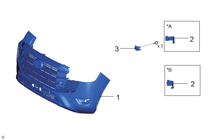
| Procedure | Part Name Code |

|

|

|
|
|---|---|---|---|---|---|
| 1 | FRONT BUMPER ASSEMBLY | - | - | - | - |
| 2 | FRONT BUMPER INNER BRACKET LH | 52149H | - | - | - |
| 3 | FOG LIGHT ASSEMBLY LH | - | - | - | - |
| *A | for Standard | *B | for Aero Type |
CAUTION / NOTICE / HINT
The necessary procedures (adjustment, calibration, initialization, or registration) that must be performed after parts are removed and installed, or replaced during fog light assembly LH removal/installation are shown below.
| Replaced Part or Performed Procedures | Necessary Procedures | Effect/Inoperative Function when Necessary Procedures are not Performed | Link |
|---|---|---|---|
| Front bumper assembly (Including removal and installation) |
w/ Parking Support Brake System:
·
Ultrasonic sensor detection angle
·
Ultrasonic sensor detection angle registration |
Parking support brake system | ( ) |
| Front television camera view adjustment | Panoramic view monitor system | () |
|
| Front television camera assembly, front bumper assembly or radiator grille |
·
Television camera view adjustment
·
Rear television camera view adjustment (for Rear camera detection system) |
Panoramic view monitor system | () |
- HINT:
-
·
Use the same procedure for the RH and LH sides.
·The procedure described below is for the LH side.
PROCEDURE

 1.REMOVE FRONT BUMPER ASSEMBLY
for Standard:
Click hereVehicle Exterior>EXTERIOR PANELS / TRIM>FRONT BUMPER (for Standard)>REMOVAL
for Aero Type:
Click hereVehicle Exterior>EXTERIOR PANELS / TRIM>FRONT BUMPER (for Aero Type)>REMOVAL
52149H 2.REMOVE FRONT BUMPER INNER BRACKET LH
for Standard:
Click hereVehicle Exterior>EXTERIOR PANELS / TRIM>FRONT BUMPER (for Standard)>DISASSEMBLY
for Aero Type:
Click hereVehicle Exterior>EXTERIOR PANELS / TRIM>FRONT BUMPER (for Aero Type)>DISASSEMBLY
3.REMOVE FOG LIGHT ASSEMBLY LH
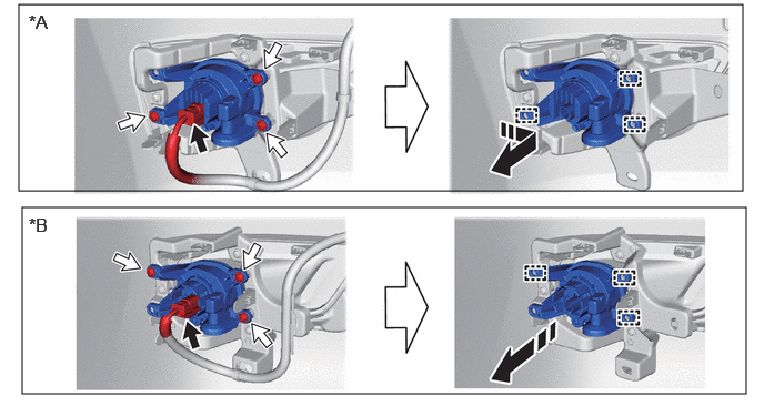
| *A | for Standard | *B | for Aero Type |

|
Remove in this Direction |

|
Connector |

|
Screw | - | - |