PARK ASSIST / MONITORING PARKING SUPPORT BRAKE SYSTEM Main Switch Circuit
DESCRIPTION
When the parking support brake cancel switch is turned on, a signal is sent to the clearance warning ECU assembly. The parking support brake system operates according to this signal.
WIRING DIAGRAM
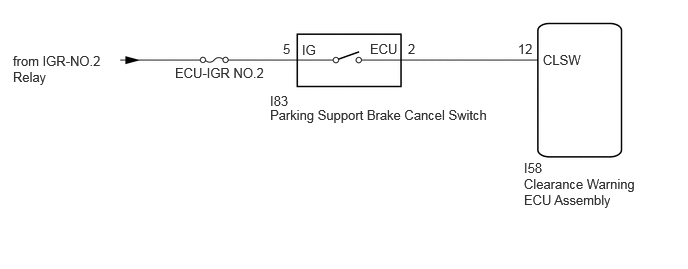
CAUTION / NOTICE / HINT
- NOTICE:
-
Inspect the fuses for circuits related to this system before performing the following procedure.
PROCEDURE
Read the Data List to check the ECU data.
- Body Electrical > Clearance Warning > Data List
-
Tester Display Measurement Item Range Normal Condition PKSB Main Switch Parking support brake system off switch input signals OFF/ON OFF: Parking support brake system off
ON: Parking support brake system on
- OK:
-
The Data List changes in response to the operation of the parking support brake cancel switch.
- Result:
-
Proceed to OK NG
OK
NG
Click hereAudio / Visual / Telematics>PARK ASSIST / MONITORING>PARKING SUPPORT BRAKE OFF SWITCH>INSPECTION
- Result:
-
Proceed to OK NG
OK
NG
Click hereAudio / Visual / Telematics>PARK ASSIST / MONITORING>PARKING SUPPORT BRAKE OFF SWITCH>REMOVAL
Disconnect the I83 parking support brake cancel switch connector.
Disconnect the I58 clearance warning ECU assembly connector.
Measure the resistance according to the value(s) in the table below.
- Standard Resistance:
-
Tester Connection Condition Specified Condition Click Location & Routing(I58,I83)Location & Routingewd_type=routing;type=c,c;code=I58,I83
I58-12 (CLSW) - I83-2 (ECU) Always Below 1 Ω I58-12 (CLSW) or I83-2 (ECU) - Body ground Always 10 kΩ or higher
- Result:
-
Proceed to OK NG
OK
NG
Disconnect the I83 parking support brake cancel switch connector.
Measure the voltage according to the value(s) in the table below.
- Standard Voltage:
-
Tester Connection Switch Condition Specified Condition Click Location & Routing(I83)Location & Routingewd_type=routing;type=c;code=I83
I83-5 (IG) - Body ground Ignition switch ON 11 to 14 V I83-5 (IG) - Body ground Ignition switch off Below 1 V
- Result:
-
Proceed to OK NG
OK
NG