AJA0F AUTOMATIC TRANSMISSION / TRANSAXLE AUTOMATIC TRANSMISSION SYSTEM(for V35A-FTS) Drive Mode Select Switch Circuit
DESCRIPTION
Each mode can be switched with the integration control & panel sub-assembly.
WIRING DIAGRAM
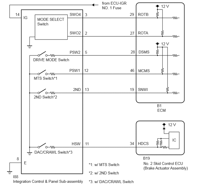
PROCEDURE
Check each symptom by checking the suspected areas in the table below.
- Result:
-
Result Proceed to DRIVE MODE switch system malfunction A MTS switch system malfunction B 2ND switch system malfunction C DAC/CRAWL switch system malfunction D
A
B
C
D
Disconnect the integration control & panel sub-assembly connector.
Turn the ignition switch to ON.
Measure the voltage according to the value(s) in the table below.
- Standard Voltage:
-
Tester Connection Condition Specified Condition Click Location & Routing(I88)Location & Routingewd_type=routing;type=c;code=I88
I88-14 (IG) - Body ground Ignition switch ON 11 to 14 V
Turn the ignition switch off.
Measure the resistance according to the value(s) in the table below.
- Standard Resistance:
-
Tester Connection Condition Specified Condition Click Location & Routing(I88)Location & Routingewd_type=routing;type=c;code=I88
I88-8 (E) - Body ground Always Below 1 Ω
- Result:
-
Proceed to OK NG
OK
NG
Click hereDrivetrain>AJA0F (AUTOMATIC TRANSMISSION / TRANSAXLE)>COMBINATION SWITCH>INSPECTION
- Result:
-
Proceed to OK NG
OK
NG
Disconnect the ECM connector.
Measure the resistance according to the value(s) in the table below.
- Standard Resistance:
-
Tester Connection Switch Condition Specified Condition Click Location & Routing(B1)Location & Routingewd_type=routing;type=c;code=B1
B1-28 (DSMS) - Body ground DRIVE MODE switch pushed 138 Ω or less B1-28 (DSMS) - Body ground DRIVE MODE switch not pushed 10 kΩ or higher
- Result:
-
Proceed to OK NG
OK
NG
Operate the DRIVE MODE switch to switch to drive mode select mode.
Operate the MODE SELECT switch.
- OK:
-
The drive mode select of the meter display changes according to the operation of the MODE SELECT switch.
- Result:
-
Proceed to OK NG
OK
NG
Disconnect the integration control & panel sub-assembly connector.
Turn the ignition switch to ON.
Measure the voltage according to the value(s) in the table below.
- Standard Voltage:
-
Tester Connection Condition Specified Condition Click Location & Routing(I88)Location & Routingewd_type=routing;type=c;code=I88
I88-14 (IG) - Body ground Ignition switch ON 11 to 14 V
Turn the ignition switch off.
Measure the resistance according to the value(s) in the table below.
- Standard Resistance:
-
Tester Connection Condition Specified Condition Click Location & Routing(I88)Location & Routingewd_type=routing;type=c;code=I88
I88-8 (E) - Body ground Always Below 1 Ω
- Result:
-
Proceed to OK NG
OK
NG
Click hereDrivetrain>JF2BM (TRANSFER / 4WD / AWD)>MULTI-TERRAIN SELECT SWITCH>INSPECTION
- Result:
-
Proceed to OK NG
OK
NG
Disconnect the ECM connector.
Measure the resistance according to the value(s) in the table below.
- Standard Resistance:
-
Tester Connection Switch Condition Specified Condition Click Location & Routing(B1)Location & Routingewd_type=routing;type=c;code=B1
B1-46 (MCMS) - Body ground MTS switch pushed 138 Ω or less B1-46 (MCMS) - Body ground MTS switch not pushed 10 kΩ or higher
- Result:
-
Proceed to OK NG
OK
NG
Operate the MTS switch to switch to multi-terrain select mode.
Operate the MODE SELECT switch.
- OK:
-
The multi-terrain select of the meter display changes according to the operation of the MODE SELECT switch.
- Result:
-
Proceed to OK NG
OK
NG
Disconnect the integration control & panel sub-assembly connector.
Measure the resistance according to the value(s) in the table below.
- Standard Resistance:
-
Tester Connection Condition Specified Condition Click Location & Routing(I88)Location & Routingewd_type=routing;type=c;code=I88
I88-8 (E) - Body ground Always Below 1 Ω
- Result:
-
Proceed to OK NG
OK
NG
Click hereDrivetrain>AJA0F (AUTOMATIC TRANSMISSION / TRANSAXLE)>COMBINATION SWITCH>INSPECTION
- Result:
-
Proceed to OK NG
OK
NG
Disconnect the ECM connector.
Measure the resistance according to the value(s) in the table below.
- Standard Resistance:
-
Tester Connection Switch Condition Specified Condition Click Location & Routing(B1)Location & Routingewd_type=routing;type=c;code=B1
B1-19 (SNWI) - Body ground 2ND switch pushed 66 Ω or less B1-19 (SNWI) - Body ground 2ND switch not pushed 10 kΩ or higher
- Result:
-
Proceed to OK NG
OK
NG
Operation conditions for downhill assist control.
Transfer position in H4
Shift lever not in P
Front differential lock and rear differential lock not selected
Accelerator pedal and brake pedal not depressed
Driving uphill at a vehicle speed of 30 km/h (19 mph) or lower
Operation conditions for crawl control.
Transfer position in L4
Shift lever not in P or N
Driver side door closed
VSC system normal
2ND start mode off
Parking brake released
Engine started
- Result:
-
Proceed to NEXT
NEXT
Disconnect the integration control & panel sub-assembly connector.
Turn the ignition switch to ON.
Measure the voltage according to the value(s) in the table below.
- Standard Voltage:
-
Tester Connection Condition Specified Condition Click Location & Routing(I88)Location & Routingewd_type=routing;type=c;code=I88
I88-14 (IG) - Body ground Ignition switch ON 11 to 14 V
Turn the ignition switch off.
Measure the resistance according to the value(s) in the table below.
- Standard Resistance:
-
Tester Connection Condition Specified Condition Click Location & Routing(I88)Location & Routingewd_type=routing;type=c;code=I88
I88-8 (E) - Body ground Always Below 1 Ω
- Result:
-
Proceed to OK NG
OK
NG
Click hereBrake>BRAKE CONTROL / DYNAMIC CONTROL SYSTEMS>CRAWL SWITCH>INSPECTION
- Result:
-
Proceed to OK NG
OK
NG
Disconnect the No. 2 skid control ECU (brake actuator assembly) connector.
Measure the resistance according to the value(s) in the table below.
- Standard Resistance:
-
Tester Connection Switch Condition Specified Condition Click Location & Routing(B19)Location & Routingewd_type=routing;type=c;code=B19
B19-34 (HDCS) - Body ground DAC/CRAWL switch pushed Below 100 Ω B19-34 (HDCS) - Body ground DAC/CRAWL switch not pushed 10 kΩ or higher
- Result:
-
Proceed to OK NG
OK
NG
Operate the DAC/CRAWL switch to switch to downhill assist control mode.
Operate the MODE SELECT switch.
- OK:
-
The target vehicle speed of the meter display changes.
- Result:
-
Proceed to OK NG
OK
for LHD:
Click hereBrake>BRAKE CONTROL / DYNAMIC CONTROL SYSTEMS>BRAKE ACTUATOR (for LHD)>REMOVAL
for RHD:
Click hereBrake>BRAKE CONTROL / DYNAMIC CONTROL SYSTEMS>BRAKE ACTUATOR (for RHD)>REMOVAL
NG