HEATING / AIR CONDITIONING AIR CONDITIONING SYSTEM Heater Water Pump Circuit
DESCRIPTION
The heater accessory assembly feeds engine coolant to the heater core assembly when the engine is stopped to prevent heating performance from decreasing. The air conditioning amplifier assembly sends the water pump ON request signal to the ECM via the CAN communication system. Upon receiving the water pump ON request signal, the ECM activates the semiconductor power integration ECU to operate the heater accessory assembly in accordance with the command from the ECM.
WIRING DIAGRAM
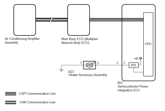
CAUTION / NOTICE / HINT
- NOTICE:
-
The air conditioning system uses the CAN communication system and CXPI communication system. Inspect the communication function by following How to Proceed with Troubleshooting.
PROCEDURE
Read the Data List according to the display on the GTS.
- Body Electrical > Power Integration No.1 > Data List
-
Tester Display Measurement Item Range Normal Condition Diagnostic Note A/C Water Pump Fuse Shut Off Status Heater accessory assembly fuse shut off status OFF/ON OFF: Fuse has no shut off history
ON: Fuse has shut off history-
- Body Electrical > Power Integration No.1 > Data List
-
Tester Display A/C Water Pump Fuse Shut Off Status - 50003 473 427
- OK:
-
OFF is displayed on the GTS.
- Result:
-
Proceed to OK NG
OK
NG
Read the Data List according to the display on the GTS.
- Body Electrical > Power Integration No.1 > Data List
-
Tester Display Measurement Item Range Normal Condition Diagnostic Note A/C Water Pump Input Signal Heater accessory assembly input signal OFF/ON OFF: Heater accessory signal not input
ON: Heater accessory signal input-
- Body Electrical > Power Integration No.1 > Data List
-
Tester Display A/C Water Pump Input Signal - 50003 473 424
- OK:
-
ON is displayed on the GTS.
- Result:
-
Proceed to OK NG
OK
NG
Read the Data List according to the display on the GTS.
- Body Electrical > Power Integration No.1 > Data List
-
Tester Display Measurement Item Range Normal Condition Diagnostic Note A/C Water Pump Output Signal Heater accessory assembly output signal OFF/ON OFF: Heater accessory assembly off
ON: Heater accessory assembly on-
- Body Electrical > Power Integration No.1 > Data List
-
Tester Display A/C Water Pump Output Signal - 50003 473 425
- OK:
-
ON is displayed on the GTS.
- Result:
-
Proceed to OK NG
OK
NG
Click hereVehicle Interior>HEATING / AIR CONDITIONING>HEATER WATER PUMP>INSPECTION
- Result:
-
Proceed to OK NG
OK
NG
Disconnect the B23 heater accessory assembly connector.
Disconnect the B57 semiconductor power integration ECU connector.
Measure the resistance according to the value(s) in the table below.
- Standard Resistance:
-
Tester Connection Condition Specified Condition Click Location & Routing(B23,B57)Location & Routingewd_type=routing;type=c,c;code=B23,B57
B23-2 (+B) - B57-3 (L) Always Below 1 Ω B23-1 (-) - Body ground Always Below 1 Ω
- Result:
-
Proceed to OK NG
OK
NG
Disconnect the B23 heater accessory assembly connector.
Read the Data List according to the display on the GTS.
- Body Electrical > Power Integration No.1 > Data List
-
Tester Display Measurement Item Range Normal Condition Diagnostic Note A/C Water Pump Fuse Shut Off Status Heater accessory assembly fuse shut off status OFF/ON OFF: Fuse has no shut off history
ON: Fuse has shut off history-
- Body Electrical > Power Integration No.1 > Data List
-
Tester Display A/C Water Pump Fuse Shut Off Status - 50003 473 427
- OK:
-
ON is displayed on the GTS.
- Result:
-
Proceed to OK NG
OK
NG
Disconnect the B23 heater accessory assembly connector.
Disconnect the B57 semiconductor power integration ECU connector.
Measure the resistance according to the value(s) in the table below.
- Standard Resistance:
-
Tester Connection Condition Specified Condition Click Location & Routing(B23,B57)Location & Routingewd_type=routing;type=c,c;code=B23,B57
B23-2 (+B) or B57-3 (L) - Other terminals and body ground Always 10 kΩ or higher
- Result:
-
Proceed to OK NG
OK
NG